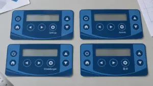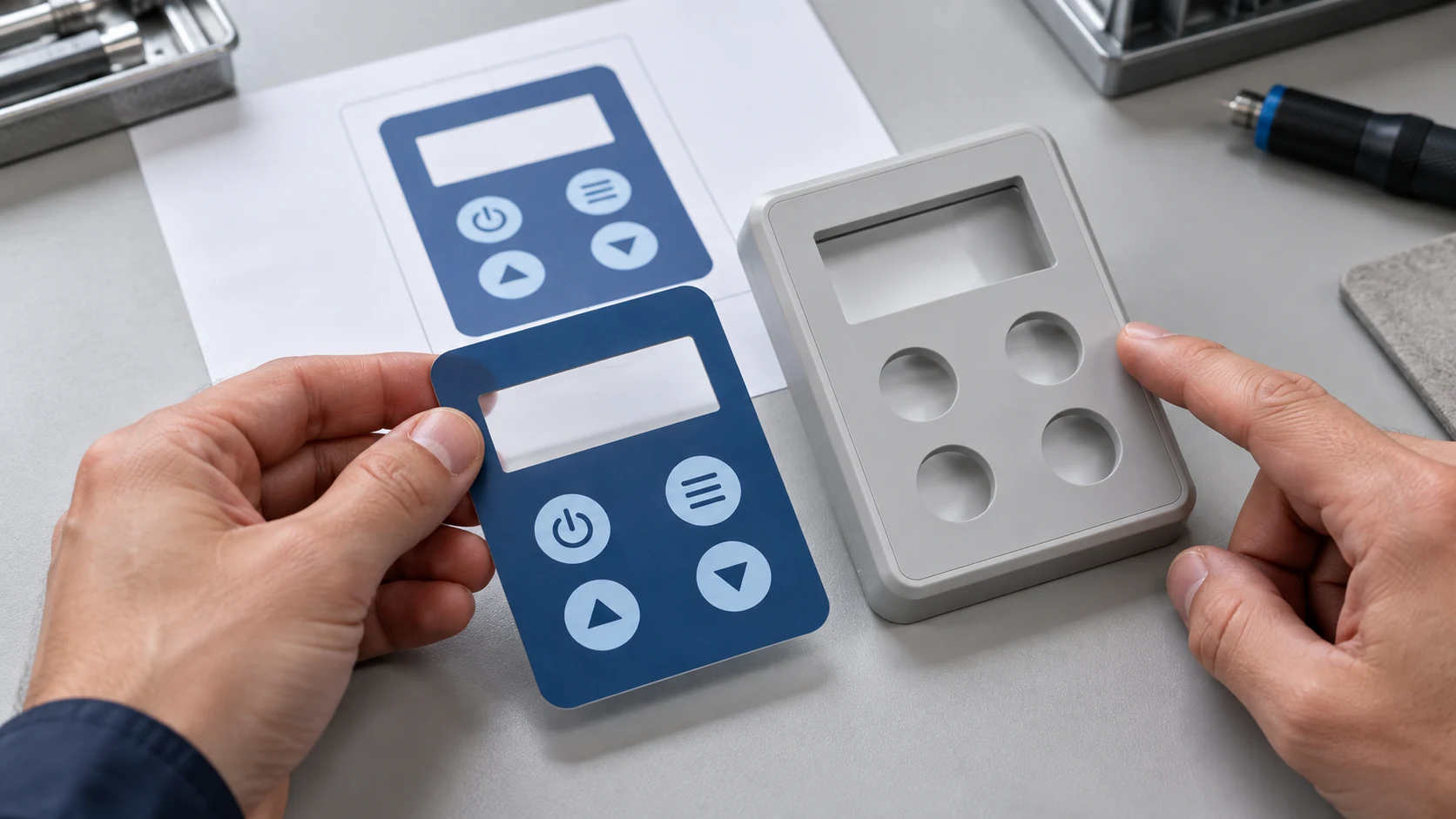
Design a custom membrane panel by defining the supplied part, documenting its operating conditions, coordinating the printed surface with the enclosure, and approving physical samples against written requirements. The release package should connect the mechanical drawing, artwork, material construction, adhesive pattern, and inspection criteria through an identifiable revision.
“Membrane panel” can describe different assemblies. This membrane panel design guide focuses on the printed graphic overlay, supplied separately or incorporated into a larger interface. Use it as a graphic overlay design guide for coordinating the front surface; circuit, matrix, and connector design remain separate tasks.
- Define Function, Supply Scope and Use Conditions
- Build a Complete Design Input Checklist
- Select Film, Finish and Total Thickness
- Specify a construction, not just a polymer name
- State where and how thickness is measured
- Plan Graphics, Windows and Embossed Features
- Coordinate artwork with the mechanical drawing
- Define each window by its optical and mechanical role
- Treat embossing as an interface feature
- Design Adhesive Patterns and Mechanical Interfaces
- Review Files, Prototypes and Production Criteria
- Stage-by-stage decision table
- Define what a sample is allowed to prove
- Keep the approved configuration traceable
- Practical Design Questions
- Can a worn sample replace the engineering drawing?
- Can several language variants share one construction?
- What should be requested before prototype and production quotations are compared?
- Request a Panel Design Review
Define Function, Supply Scope and Use Conditions
Start with a boundary drawing or written scope statement. Do not assume that everyone quoting a “panel” is quoting the same item.
| Supply scope | Define before requesting a quotation |
|---|---|
| Graphic overlay only | Printed film, windows, forming, cutouts, rear adhesive, removable liners, and any separately supplied items. |
| Complete membrane switch | The overlay plus the agreed electrical and switching construction; assign responsibility for the overlay-to-switch interface. |
| Panel with mechanical components | Identify the backing panel, lens, gasket, housing, or other parts included, and who assembles and validates them. |
For an overlay-only requirement, the custom graphic overlays product page provides the relevant commercial starting point. Identify separately who supplies the display, keys, support structure, and enclosure.
Describe what the operator actually does: views information, presses through the film, locates controls by feel, or uses a separate touch-sensing system. Raised graphics do not by themselves establish an electrical function or guarantee a tactile snap. Confirm those requirements with the owner of the underlying interface.
Replace broad descriptions such as “outdoor” or “easy to clean” with operating conditions. Record exposure duration, cleaning products, wiping method, gloves, viewing position, and service expectations. Distinguish normal operation from storage, transport, and temporary exposure. Assign an owner to requirements that span the overlay and the finished equipment.
Build a Complete Design Input Checklist
Use the checklist as a working document. Record a requirement, supporting file, responsible person, and status for each applicable row. Mark non-applicable items explicitly. Early discussions can start with incomplete information, but a production release needs an agreed disposition for every applicable requirement.
| Input | Information to record |
|---|---|
| Project identification | Part number, description, drawing and artwork revisions, date, and engineering, purchasing, and quality contacts. |
| Supply boundary | Overlay-only, complete switch, or mechanical assembly; included components, exclusions, assembly owner, and validation owner. |
| Operator interaction | Viewing or actuation, key locations, gloves, access angle, operating frequency, and required service duration. |
| Environment | Operating, storage, and shipping temperatures; humidity, condensation, sunlight, splash, immersion, dust, and exposure duration where applicable. |
| Cleaning and chemicals | Product names or compositions, concentrations, contact times, wiping materials, frequency, and any rinsing or drying procedure. |
| Mechanical envelope | Finished outline, datums, units, tolerances, recess depth, mounting surface, holes, cutouts, corner geometry, and available thickness. |
| Film and finish | Candidate grade or performance requirements; texture, gloss, coating, print side, and separate requirements for viewing and pressing zones. |
| Graphics and language | Editable artwork, reference proof, approved wording, symbols, language variants, orientation, and part-identification content. |
| Color and appearance | Physical color reference, viewing conditions, backing, finish, cosmetic zones, and an agreed evaluation method. |
| Windows and lighting | Display active area and location, clear or tinted regions, open cutouts, light source, viewing angles, and lit/unlit appearance requirements. |
| Formed features | Embossed locations, profiles, heights and datums, underlying actuator positions, movement clearances, and alignment requirements. |
| Adhesive and substrate | Housing material and coating, surface texture, bond pattern, keep-outs, installation conditions, liner arrangement, and service-removal needs. |
| Interface ownership | Owners of display alignment, key response, touch sensing where used, enclosure sealing, and final equipment verification. |
| Acceptance and documentation | Inspection methods, conditions, pass/fail limits, sample quantities, required reports, and applicable document or standard editions. |
| Purchasing and lifecycle | Prototype and production quantities, order profile, variants, packing, identification, storage instructions, change notification, and approval authority. |
Keep performance targets separate from evidence. A required cleaning schedule belongs in the specification; a material supplier’s chemical-resistance statement belongs in the supporting evidence. Record how the finished construction will be assessed before treating either as an accepted design.
Select Film, Finish and Total Thickness
Specify a construction, not just a polymer name
Polyester and polycarbonate are starting categories, not complete specifications. Compare candidate film grades against the intended bending, forming, cleaning, optical, and environmental requirements. Record the coating and print-receptive surface as well as the base film.
For example, MacDermid Alpha distinguishes textured, gloss, antiglare, and application-specific options within its hardcoated interface films. A property associated with one construction should not be assigned to every film sharing its polymer name.
Review the graphic overlay material selection guide for material-level decisions. For this design review, record why the selected construction addresses the actual requirement and what remains to be demonstrated on samples.
Do not prescribe one surface finish across every zone without checking its purpose. Compare a viewing window over the actual display, a key area during operation, and a branding area against its cosmetic reference. Specify whether the finish is inherent to the film or applied selectively.
State where and how thickness is measured
Define the installed flat thickness as the sum of the permanent layers present at a specified cross-section. Include film, relevant coatings and print layers, adhesive, and any permanent carrier or support supplied within the scope. Avoid double-counting a coating already included in a supplier’s stated film thickness.
Exclude removable release liners and temporary protective films from the installed dimension. Record shipping thickness separately when handling requires it. Call out local emboss height, lens thickness, and gasket compression independently rather than hiding them inside one nominal number.
Use tolerances to review both the shallowest available recess and the thickest permitted construction. Identify whether a gasket or adhesive is measured before or after the defined assembly process. A nominal fit alone is not a release criterion.
Plan Graphics, Windows and Embossed Features
Coordinate artwork with the mechanical drawing
Establish common datums and an explicit viewing side. Separate printed artwork, finished cuts, windows, formed features, and adhesive geometry so a manufacturing boundary cannot be mistaken for a printed line.
Use editable vectors for text, icons, and outlines where practical, alongside a reference proof showing the intended appearance. Convert production text to outlines or agree another controlled font-handling method. Check the exported proof for missing elements, incorrect orientation, and substituted characters.
Agree file format, bleed, trapping, minimum features, and print registration with the intended manufacturing process. Do not treat another project’s settings as universal limits. Identify which document controls each characteristic; conflicting drawing and artwork dimensions should be resolved by a recorded revision, not an undocumented interpretation.
For color-critical areas, request a physical sample on the intended film and print construction, evaluated from the user-facing side against the agreed reference. A screen proof can approve wording and layout, but it is not a physical color, texture, or opacity standard.
Define each window by its optical and mechanical role
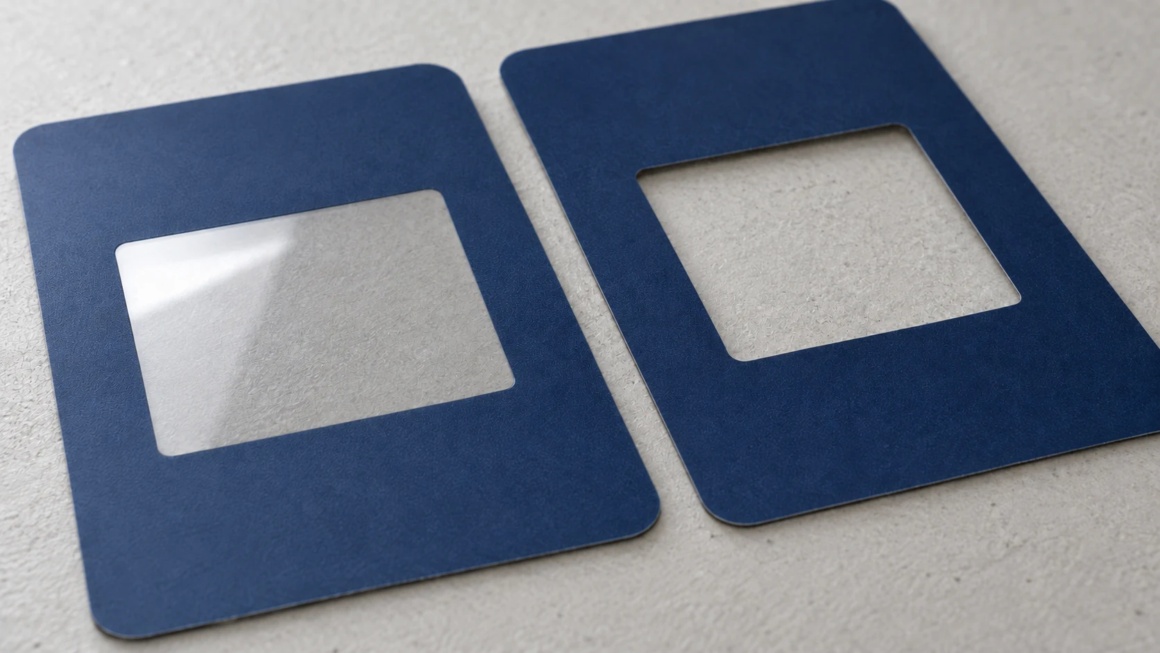
Distinguish a transparent area in continuous film from an opening cut through that film. The drawing should identify which is required, what lies behind it, and who supplies any separate lens or seal.
Locate the display’s active area, printed border, housing opening, and mounting datums independently. Review their relative movement within the permitted tolerances. Check readability from the specified viewing positions using the intended display-to-overlay spacing, not just a printout placed directly behind the film.
For dead-front icons, separate light-blocking regions from controlled-transmission regions. Define the required appearance with the light source off and on, together with ambient lighting and viewing conditions. A black artwork swatch alone does not specify the optical behavior of the printed stack.
Treat embossing as an interface feature
Membrane overlay design must coordinate formed features with the supporting interface. Specify the feature profile, location, height reference, and alignment to the underlying actuator or contact zone. Where the overlay moves during use, evaluate the formed film, coating, print, support, and adhesive pattern together.
Test representative samples in the intended supporting construction. Record interference, incomplete return, whitening, cracking, or an unexpected change in key response. Do not approve a formed feature solely because its loose-part appearance matches the drawing.
Design Adhesive Patterns and Mechanical Interfaces
For custom control panel overlay design, select the adhesive for the actual bonding surface, not only for a generic label such as “plastic” or “painted metal.” Identify the housing grade, coating, texture, and assembly preparation. Include a representative housing sample when those details cannot be communicated adequately on a drawing.
As one material-specific example, the 3M 467MP technical data sheet separates application guidance from environmental performance and describes its data as typical rather than specification limits. Use the instructions for the adhesive actually selected; do not convert a raw adhesive property into an installed-panel guarantee.
Show the bond pattern and its exclusions. Identify optical regions, moving key areas, separate sealing features, openings, and liner pull tabs. The approved construction may use adhesive within an optical region, but that must be a deliberate optical-bonding decision rather than accidental coverage by mounting adhesive.
Review the intended assembly sequence: locating the part, removing the liner, applying pressure to supported areas, and inspecting the bonded interface. Specify surface preparation, application conditions, and the interval before testing according to the selected materials and validated process. Avoid applying an installation force through an unsupported display region.
Check the tolerance chain across printed features, cut edges, formed features, housing location, and display position. If permitted relative displacement consumes the required masking overlap or clearance, revise the geometry, locating method, or agreed tolerances before tooling.
Treat moisture protection as an assembly requirement. Map the actual boundary, including edges, openings, lenses, fasteners, and adjoining components. Specify the test article and acceptance conditions. An overlay or adhesive selection alone does not establish the finished equipment’s ingress performance.
Review Files, Prototypes and Production Criteria
Use separate approvals for intent, appearance, fit, and performance. A digital proof, a loose printed sample, and a production-representative assembly answer different questions.
Stage-by-stage decision table
The open-issues column identifies project questions to resolve, not permission to release incomplete specifications. Give each issue an owner and closure action. Any limited approval should state exactly which work may proceed and which characteristics remain unapproved.
| Stage | Information to submit | Acceptance or approval action | Open issues to record |
|---|---|---|---|
| Scope and requirements | Supply statement, input checklist, application notes, available drawings. | Agree boundaries, requirement owners, and the basis for quotation or concept work. | Missing exposure details, uncertain interfaces, unavailable mating parts. |
| Construction review | Candidate materials, cross-sections, thickness budget, housing information, adhesive pattern. | Agree the proposed construction and the evidence needed to evaluate it. | Material alternatives, test responsibility, installation constraints. |
| Drawing and artwork review | Coordinated drawing, editable artwork, reference proof, feature layers, revision record. | Approve dimensions, wording, orientation, layer interpretation, and process-specific file requirements. | Conflicting revisions, artwork exceptions, unagreed tolerances. |
| Appearance and fit samples | Identified samples, physical color reference, dimensional results, representative mating parts. | Approve or reject appearance and fit separately; record deviations. | Sample-to-production differences, optical alignment, forming or assembly changes. |
| Application validation | Production-representative construction, test plan, conditioning details, and results. | Assess cleaning, bonding, viewing, operation, and relevant environmental requirements. | Failed requirements, incomplete tests, changes requiring repeat evaluation. |
| Production release | Released files, material list, approved sample references, inspection plan, packaging requirements. | Authorize the defined revision and close release-blocking issues. | Approved deviations, remaining restrictions, and change-notification obligations. |
Define what a sample is allowed to prove
Before ordering samples, write down their purpose. A layout model can assess graphic placement. A printed sample can support appearance review. Fit, bonding, key interaction, and environmental checks require the relevant construction and mating components.
Identify differences from production, including film, coating, ink, forming, cutting, adhesive, and assembly method. Do not carry an approval across an unassessed difference merely because both samples share the same artwork revision.
For each acceptance characteristic, record the test article, method, conditioning, measurement location, evaluation conditions, and pass/fail rule. Define cosmetic zones and viewing conditions for visible defects. Assess windows with the specified display or light source; assess a moving overlay with the specified supporting interface.
After cleaning or environmental exposure, inspect the characteristics that matter to the application: legibility, surface condition, optical appearance, bonding, fit, and operating behavior where applicable. Distinguish an observed failure from a diagnosed cause. Edge lift, for example, is a finding to investigate rather than proof that changing the adhesive alone will resolve the problem.
Keep the approved configuration traceable
A useful sample approval record contains the part number, sample identifier, drawing revision, artwork revision, material construction, mating-part revision, inspection results, deviations, approval scope, approver, and date. Retain the agreed physical reference where appearance or feel cannot be fully represented by a drawing.
Before repeat production, compare the order against that released configuration. Review substitutions and changes to material, print, adhesive, tooling, artwork, or mating parts for their effect on the original approval. Specify the evidence needed to accept a change rather than treating “equivalent material” as a complete technical explanation.
Practical Design Questions
Can a worn sample replace the engineering drawing?
Use it as reference evidence, not as the only dimensional or color authority. Record wear, shrinkage, damage, missing components, and uncertain history. Reconcile the replacement specification with the mating equipment and approve a new controlled drawing and appearance reference.
Can several language variants share one construction?
Review them together, then control each artwork variant separately. Check wording, symbol meaning, available space, identification, and the relationship to the equipment’s functions. A shared outline does not establish that every language version has been approved.
What should be requested before prototype and production quotations are compared?
Request the supply scope, construction, sample purpose, tooling assumptions, required inspections, and deliverables behind each quotation. Confirm whether prototype approvals can be carried forward to production or whether construction changes require additional review. Compare the same deliverable rather than only the quoted part description.
Request a Panel Design Review
Share the available panel dimensions, enclosure information, artwork or sketch, operating environment, window and key requirements, and expected quantities with JASPER. State whether you need only the printed overlay or a broader assembly.
Materials and drawings do not need to be fully selected to describe the project. Explain the constraints and the decisions that need review, so the discussion can focus on the appropriate supply scope, interfaces, and sample approval requirements.
Ready to Start Your Project?
Tell us about your membrane switch, keypad, or graphic overlay requirements. Our engineering team will review your specifications and provide a detailed quote.