PCB fabrication produces the bare board; PCB assembly fits and connects its components. For OEM buyers comparing PCB fabrication vs assembly, the practical boundary is the deliverable and its acceptance evidence. Order fabrication when the requirement is an approved bare PCB. Order assembly when the requirement is a populated board with specified verification. Use one approved release manifest to connect PCB revision, assembly revision, build variant and acceptance records, even when a single supplier handles both scopes.
- Fabrication Produces the Board; Assembly Populates It
- Match Each Handoff Item to Its Owner
- Fabrication Data: Layers, Drills and Board Requirements
- Choose the Transfer Format, Then Define the Content
- Assembly Data: BOM, Placement and Build Notes
- The BOM Controls Component Identity
- Placement Data Controls Location and Orientation
- Build Notes Control Exceptions
- Where Board Acceptance Hands Over to Assembly
- Fabricator Release: Evidence for the Bare Board
- Assembler Receiving: Evidence for Suitability
- Assembly Release: Evidence for the Populated Board
- How Changes Propagate Across Two Purchase Scopes
- Separate Discovery from Root-Cause Ownership
- A Split-Supplier Handoff Without Missing Ownership
- Which Scope Wins Under Your Project Constraints?
- Where a Fabrication Scope Wins
- Where an Assembly Scope Wins
- Route the Order by Constraint
- Final Recommendation: Release Both Scopes Deliberately
Fabrication Produces the Board; Assembly Populates It
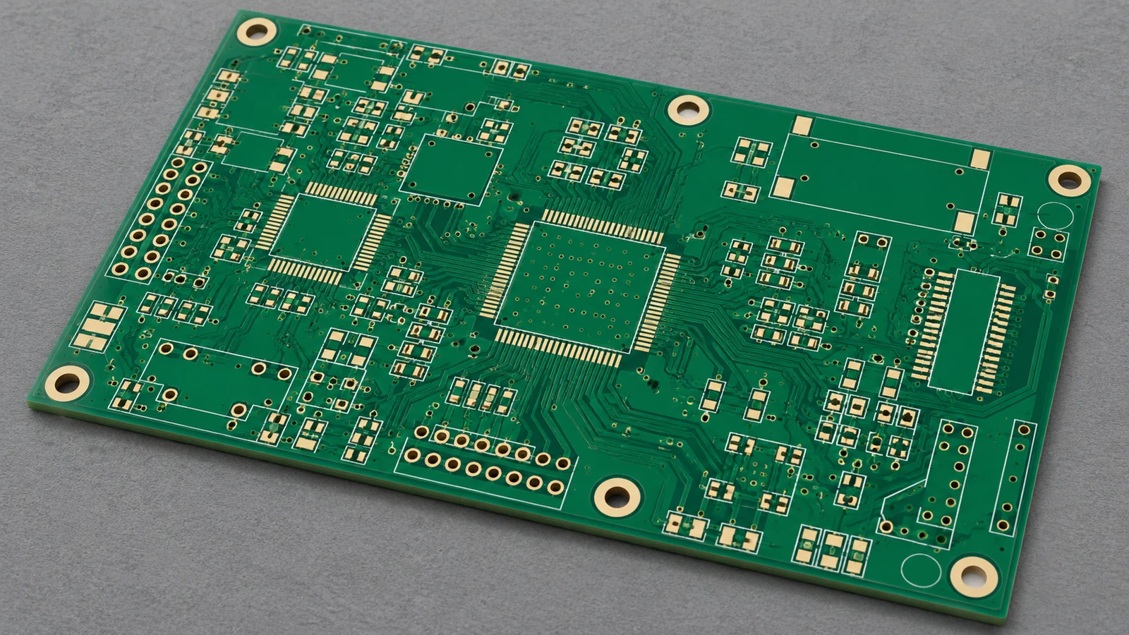
PCB fabrication and PCB assembly require different purchasing scopes because they deliver different physical objects. Fabrication supplies the conductive board structure. Assembly adds the specified components and connections, followed by the inspection and testing included in the order. Buying both from one company changes the coordination route, but each deliverable still needs defined acceptance criteria.
| Required Deliverable | Correct Purchase Scope | Evidence to Request |
|---|---|---|
| Bare boards for an internal assembly line | PCB fabrication | Board identity, lot records and specified bare-board acceptance results |
| Populated boards using customer-owned PCBs | PCB assembly | Incoming-board release, build records and specified assembly verification |
| Populated boards with board supply included | Fabrication plus assembly | Traceable evidence for both the supplied PCB and completed PCBA |
| Another component variant on an unchanged board | Assembly variant, subject to design approval | Approved BOM variant and confirmation of PCB compatibility |
The fabrication drawing answers what board must be made. The assembly drawing answers what must be fitted and how. A fabricator can demonstrate that delivered copper matches the released netlist, while the assembler must establish that the correct components were fitted and that any ordered powered tests met the product limits. Each result has a defined scope.
Match Each Handoff Item to Its Owner
The following matrix assigns functional ownership for a typical OEM-controlled design. The accepted contract should name the responsible organization and approver for each function.
| Handoff Item | Fabrication Scope | Assembly Scope | Owning Function | Acceptance Evidence |
|---|---|---|---|---|
| Copper and drill data | Produce the released layers, holes and profile | Use matching geometry for placement and tooling | OEM PCB design; fabricator executes | Approved fabrication release and ordered dimensional/electrical records |
| Board material requirements | Supply the specified construction and finish | Confirm compatibility with the planned assembly process | OEM design/material approval; fabricator and assembly engineering review | Approved stack-up, material declaration and required lot evidence |
| Component BOM | No mounted-component purchasing in a bare-board-only order | Identify fitted parts, variants and authorized substitutions | OEM component engineering; assigned purchasing party | Approved BOM revision and traceable build material records |
| Placement instructions | Provide the board geometry and markings as released | Translate position, side and orientation into the assembly setup | OEM design; assembly engineering | Approved assembly drawing and setup/first-build verification |
| Bare-board acceptance | Verify the supplied PCB against its purchase specification | Inspect incoming boards to the agreed receiving plan | Fabricator quality; assembler receiving quality | Lot-linked release records and receiving disposition |
| Assembled-board verification | Provide board evidence for any investigation | Verify workmanship and perform the ordered tests | Assembly quality; OEM owns acceptance requirements | Inspection records and specified test results |
| Production panel | Fabricate the approved panel | Confirm handling, tooling and depanelization compatibility | Assigned panel owner; both suppliers approve interfaces | Approved panel drawing and incoming identity check |
Fabrication Data: Layers, Drills and Board Requirements
A fabrication package defines the bare PCB that the fabricator must deliver: its conductive layers, holes, outline, construction and acceptance requirements. Identify the PCB part number and revision. A ZIP filename cannot establish which drawing, stack-up or approved deviation controls the order.
An export can be valid but incomplete. The fabrication drawing must resolve the material requirement, finished thickness and tolerance, copper requirements, surface finish, hole requirements, dimensional datums and any specified impedance controls so the fabricator can determine the required construction and the buyer can accept the delivered board. Identify plated and non-plated holes explicitly.
Choose the Transfer Format, Then Define the Content
The main exchange paths are Gerber with companion files, ODB++, and IPC-2581. Agree a supported path before release. The file extension does not establish completeness.
| File or Dataset | Fabrication Content | Assembly Relevance | Release Control |
|---|---|---|---|
| Gerber layer data | Copper, solder mask, legend and profile information | Geometry supports assembly preparation; ordinary fabrication layers do not define the fitted BOM | Name layer functions and the controlling PCB revision |
| Excellon or supported Gerber drill/route data | Hole and machining coordinates with the required interpretation | Finished holes must suit the approved component leads and mounting features | Define units, hole plating and finished requirements |
| ODB++ | Structured board manufacturing data | Can also carry component and other assembly information | Confirm the actual exported content and receiver support |
| IPC-2581 | Structured PCB manufacturing description | Can include assembly description data | Confirm export content, supported revision and receiving interpretation |
Ucamco describes Gerber layer and job-file responsibilities. ODB++Design and IPC-2581 support information spanning fabrication and assembly. A richer dataset can reduce separate exports, but the order still needs an approved BOM, build definition and acceptance plan.
Paste-layer artwork illustrates the boundary. It may travel with the board export, yet it is an input to stencil preparation for assembly. Put stencil design and aperture-change approval with the agreed assembly engineering owner. Similarly, obtain assembler approval of production-panel handling features before the fabricator commits to the panel.
For release identification, use the PCB part number, PCB revision, fabrication-drawing revision, stack-up reference and applicable change authorization. Keep an export timestamp as supporting information. It is not the product revision.
Assembly Data: BOM, Placement and Build Notes
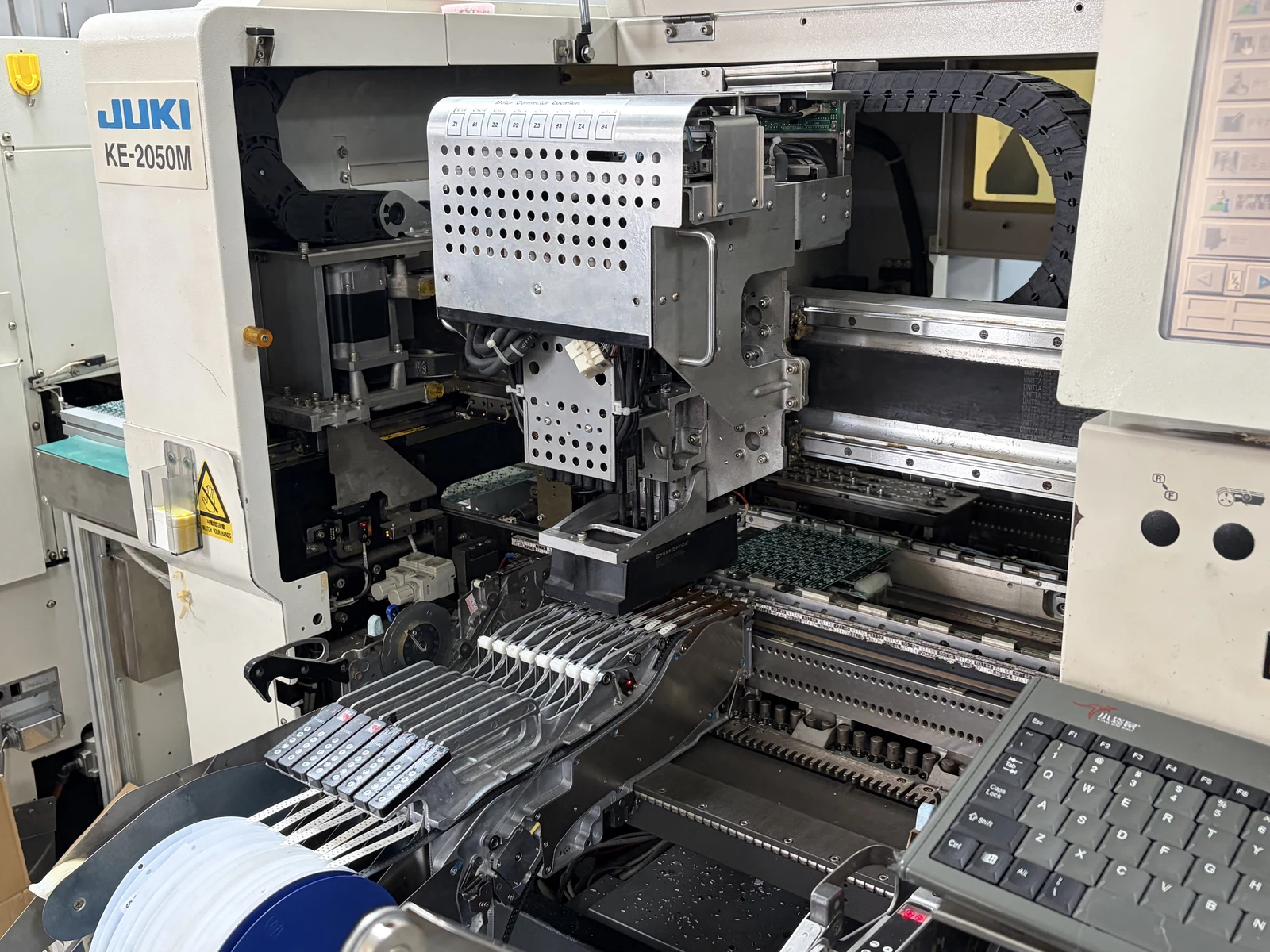
An assembly package defines the populated product, including which components are fitted, where they go, which variant is built and how the completed board is accepted. Supply the approved BOM, placement data and assembly drawing with build notes, plus programming and test requirements when those operations are ordered.
The BOM Controls Component Identity
The bill of materials should identify manufacturer, full manufacturer part number (MPN), reference designators, quantity per board and package. Record approved alternatives and do-not-populate positions against the build variant. A value is not a purchasing identity: two capacitors with the same capacitance can have different packages, voltage ratings and dielectric characteristics, so the BOM must identify the approved part or a controlled specification that resolves those differences.
Keep the sourcing decision explicit. A BOM tells the assembler what the design requires; it does not automatically authorize component purchasing or substitution. The OEM should identify who buys the components and who approves an alternative. A bare-board-only fabrication order does not include that responsibility.
Placement Data Controls Location and Orientation
The component placement list, also called CPL, centroid or pick-and-place data, connects each reference designator to X/Y coordinates, board side and rotation. These are the distinct functions described in Eurocircuits’ BOM and CPL guidance.
Declare the coordinate system. State whether coordinates use mm or inches, identify the origin and axes, and define the viewing convention for bottom-side parts. Rotation is expressed in degrees and needs a defined package orientation. For example, an illustrative CPL entry for U3 might specify X = 12.50 mm, Y = 8.00 mm, Top and 90 degrees relative to the approved footprint’s zero orientation. The angle alone is insufficient. Check pin 1 and polarity against the assembly drawing during setup.
For a concrete export example, KiCad 9.0 offers ASCII, CSV and Gerber X3 placement outputs. Its origin and component-exclusion settings affect what reaches manufacturing. KiCad’s PCB Editor documentation describes those options. Agree the export convention with the receiving assembler.
Gerber X3 deserves a precise distinction: its component layers can carry assembly information. Ordinary copper, mask and legend files alone cannot define a complete assembly order. Ucamco’s component-data specification documents this extension.
Build Notes Control Exceptions
Use the assembly drawing to specify polarity, connector orientation, height or seating requirements, and operations not resolved by placement data. Name the assembly part number, revision, BOM revision and variant; identify firmware and test-procedure revisions separately. CSV or XLSX can carry the agreed BOM. A PDF drawing communicates build instructions, but a picture alone should not be the procurement master.
Where Board Acceptance Hands Over to Assembly
Bare-board acceptance establishes that the supplied PCB meets its purchase requirements; assembly receiving acceptance establishes that the delivered lot is identified, acceptable under the receiving plan and suitable for the approved build. Assign both decisions. Receiving inspection does not transfer responsibility for a fabrication defect to the assembler or prove that every latent defect has been detected.
Fabricator Release: Evidence for the Bare Board
For rigid boards, IPC-6012, Qualification and Performance Specification for Rigid Printed Boards, defines the qualification and performance requirements, while IPC-A-600, Acceptability of Printed Boards, supports interpretation of acceptable and nonconforming conditions. Name the editions in the order. Specify the required product class and additional requirements. The public IPC-6012F scope explains the relationship.
Request the ordered evidence. A certificate of conformity (CoC) should identify the PCB and lot; provide bare-board electrical-test evidence and any dimensional, impedance or material records specified by the order. A CoC does not replace an ordered test report. Agree whether receiving inspection repeats a test or accepts the fabricator’s recorded result.
Assembler Receiving: Evidence for Suitability
The receiving plan should cover PCB part number and revision, lot identification, quantity, packaging condition and visible damage or contamination. For the intended assembly line, check the specified finish and critical mechanical features, including panel geometry, tooling features and any flatness requirement that affects how the board is supported, handled or presented for placement.
Review storage history and moisture handling against the board construction and supplier instructions. A bake cycle needs a technical basis. For unexplained discoloration, damaged packaging or a revision mismatch, hold the affected lot. The assigned technical owner must decide its disposition before release.
Assembly Release: Evidence for the Populated Board
J-STD-001, Requirements for Soldered Electrical and Electronic Assemblies, addresses soldered-assembly materials and process requirements; IPC-A-610, Acceptability of Electronic Assemblies, addresses assembly acceptability. IPC’s assembly-standard guidance describes these roles. Functional testing remains a separate requirement.
Define required inspection coverage and any electrical or functional tests, with conditions, pass/fail criteria and reporting. AOI examines the features its inspection program covers. It does not demonstrate every circuit function or hidden connection. Preserve the link from the assembly result back to the board lot, assembly revision and build variant so a failure can be investigated across both scopes.
How Changes Propagate Across Two Purchase Scopes
A design change must reach every purchase scope that depends on the changed feature. PCB and assembly revisions can advance independently, but the approved release must identify their compatible combination. Matching revision letters alone cannot establish compatibility, especially when one bare board supports several populated variants.
Consider this illustrative release relationship; these are example identifiers, not a production record.
| Controlled Field | Illustrative Entry | What It Identifies |
|---|---|---|
| PCB Part Number / PCB Revision | CTL-410 / C | The manufactured bare-board definition |
| Assembly Part Number / Assembly Revision | PCA-410 / D | The populated product definition |
| BOM Revision / Build Variant | D2 / SENSOR | The approved component population |
| Assembly Drawing / Drawing Revision | AD-410 / B | Orientation and special build instructions |
| Test Procedure / Procedure Revision | TP-410 / A | The ordered verification method and limits |
Changing C17 to an approved alternative may require a BOM and assembly-release change while leaving CTL-410 Rev C unchanged. Review package fit, electrical characteristics and assembly-process implications before approving that combination. The board revision need not move.
Changing C17’s land pattern changes the fabricated copper. Before either supplier proceeds, the OEM must release the new PCB definition and compatible assembly package, with any resulting changes to solder-mask openings, paste data, placement preparation and inspection setup addressed by the responsible engineering owners. Existing stock needs a disposition.
Separate Discovery from Root-Cause Ownership
The assembler should contain a footprint problem discovered during setup or production and provide the evidence needed to compare the board, component and approved design. The design authority leads correction of an incorrect released footprint. The fabricator leads correction when the produced geometry fails the approved fabrication requirements. Assembly engineering leads correction when the wrong placement program or component was used.
Commercial liability follows the agreed purchase terms. Record the affected lots, rework authorization and cost responsibility, then decide whether existing boards can be used, reworked, restricted to a variant or rejected before work resumes.
Keep one change authority for approving the resulting product definition. Suppliers can propose a correction; a production-side adjustment should not quietly become a new OEM design release.
A Split-Supplier Handoff Without Missing Ownership
A split-supplier build needs a named owner for the interface between board delivery and assembly release. Assign the OEM product-definition approver, the fabricator’s quality contact and the assembler’s receiving authority. Each controls a different decision. Name the person who closes disagreements before components are committed.
For a controlled OEM build, use one approved release manifest as the handoff reference. It should bind the PCB part number and revision to the assembly part number and revision, BOM variant, assembly drawing, test requirements and approved exceptions. Link the receiving record to that manifest and the delivered board lot.
The handoff can follow this sequence:
OEM approves PCB definition + assembly definition + acceptance plans
    -> Fabricator builds the PCB and releases lot-linked evidence
    -> Assembler checks delivered boards against the receiving plan
    -> Accepted lot is assigned to the approved assembly revision/variant
    -> Assembler builds, inspects and performs the ordered tests
    -> Finished PCBA ships with agreed identity and acceptance records

Any mismatch -> hold affected material -> named owner approves disposition
            -> update the controlled release or reject the affected material
Before shipment, identify who approves the production panel, who arranges transport, where receiving records go and who can authorize a concession. Record the receiving decision. A shipment notification establishes that boards were sent; it does not establish that the assembler accepted them.
Make the evidence travel with the boards. When the OEM arranges direct delivery, the fabricator should send the receiving team the PCB identity, lot information, approved deviations and required acceptance records before arrival, even if the OEM owns the inventory and neither supplier issues the other a purchase order.
The most useful procurement question is concrete: can the receiving team identify the approved assembly build for this exact PCB lot and retrieve the evidence needed to release it? Resolve that question before the line is scheduled.
Which Scope Wins Under Your Project Constraints?
Fabrication wins when the purchased deliverable is the bare PCB; assembly wins when the purchased deliverable is the populated board. Many OEM projects require both. The useful choice in PCB fabrication vs assembly is which scope to buy, who controls the interface and what evidence completes each order.
Where a Fabrication Scope Wins
Choose a fabrication-only order when the OEM has an internal assembly line or an already nominated assembler and needs independent control of the bare-board source. The deliverable remains the approved PCB, even if the fabricator also offers assembly services.
Control the board definition, material requirements, panel interface and bare-board acceptance records. Completion means the ordered boards and evidence have been accepted. It does not mean that components have been purchased, placement has been programmed or a working circuit has been verified.
Where an Assembly Scope Wins
Choose an assembly order when the OEM needs a populated board delivered to an agreed build definition. Existing customer-owned PCBs can feed that order, or PCB supply can be included as an explicitly assigned part of the scope.
Control the BOM, placement instructions, build notes, sourcing responsibilities and acceptance plan. Completion means the populated boards meet the ordered inspection and test requirements. If the assembler also procures the PCB, retain board-lot traceability and the underlying fabrication requirements.
Route the Order by Constraint
| Project Constraint | Scope to Request | Decision Before Release | Completion Evidence |
|---|---|---|---|
| OEM assembles in-house | Fabrication | Approve board construction and production panel with the internal line | Bare-board release and incoming acceptance |
| Approved bare PCBs already exist | Assembly using supplied boards | Establish lot identity, storage condition and compatible assembly revision | Receiving release plus PCBA verification |
| OEM needs populated boards from one purchasing contact | Fabrication and assembly in one defined order | Assign PCB procurement and component procurement explicitly | Traceable records for both scopes |
| Several variants use the same PCB | Assembly by controlled variant | Approve the BOM and do-not-populate definition for each variant | Variant-specific build and test records |
| Separate board and assembly suppliers are required | Separate orders with a shared release manifest | Name panel, receiving and deviation owners | Linked supplier-release and receiving records |
| Material, footprint or panel geometry changes | Review both affected scopes | Approve the impact on existing boards, tooling and assembly setup | Authorized change and material disposition |
Compare quotations against these completion conditions. Require explicit coverage of PCB supply, components, assembly operations, inspection, programming and testing where applicable, because an omitted operation can remain outside the quotation even when the supplier describes the overall service as PCB assembly. Read the exclusions before comparing totals.
Frequently Asked Questions
PCB fabrication and assembly questions are best resolved by identifying the purchased object, the approved build definition and the owner of each acceptance decision. These answers apply to the data and responsibility boundary between the two scopes.
Can Gerber files alone be used to assemble a PCB?
Ordinary fabrication Gerber files alone do not define a complete assembly build. The assembler needs component identities, placement, variant and build requirements. Gerber X3 can carry component information, but the delivered package must still contain the approved build definition, purchasing instructions and acceptance requirements.
Who checks bare-board suitability before assembly?
The assembler’s receiving and manufacturing teams check suitability under the agreed receiving plan, while the fabricator remains responsible for supplying conforming boards. The OEM defines the required board and product characteristics. Assign the team that can hold a suspect lot and the authority that can approve its disposition.
Does PCB fabrication include component purchasing?
A bare-board-only fabrication order does not include purchasing components for assembly. Component sourcing belongs to an explicitly agreed procurement scope, whether handled by the OEM, assembler or another assigned party. A company offering both services still needs a clear order defining which components it is authorized to buy.
Who owns a footprint problem found during assembly?
Ownership follows the cause and the agreed contract, rather than the stage where the problem was discovered. The design authority addresses an incorrect released footprint; the fabricator addresses nonconforming board geometry; the assembler addresses incorrect setup or component use. Contain affected material first, then authorize correction and disposition.
Should fabrication and assembly share the same revision identifier?
They should share a controlled release relationship, but their revision identifiers do not have to be identical. A single PCB revision can support several assembly variants or BOM revisions. Record the approved combination of PCB identity, assembly identity, BOM variant and applicable instructions in the release manifest.
Can fabrication and assembly data be delivered in one package?
Yes, one controlled package can contain both scopes. ODB++ and IPC-2581 can carry fabrication and assembly information, and a conventional package can combine Gerber, BOM and placement files. Confirm what was exported and what the receiver supports, then identify the approved documents and acceptance requirements for each scope.
What evidence should accompany bare boards sent to an assembler?
Send the PCB part number and revision, lot identity, approved deviations and the acceptance records required by the order. These may include a certificate of conformity and specified electrical, dimensional or impedance results. The assembler also needs the compatible assembly release and the agreed receiving criteria before using the lot.
Does assembly acceptance automatically include functional testing?
No, functional testing must be included in the agreed assembly scope and test plan. Workmanship inspection and bare-board electrical testing answer different questions from circuit-function verification. Specify the required test conditions, pass/fail limits, procedure revision and records, together with programming requirements when relevant to the build.
Final Recommendation: Release Both Scopes Deliberately
Buy fabrication against a controlled PCB definition and bare-board acceptance plan. Buy assembly against a controlled BOM, placement and build definition, with its own inspection and test requirements. Connect those scopes through one approved release manifest and a named receiving owner.
For a JASPER enquiry, prepare the board manufacturing package, BOM, placement data and assembly notes. State whether PCB supply and component purchasing are included, identify supplied-board lots where applicable, and describe the required acceptance evidence. JASPER’s PCB assembly services provide the relevant route for discussing an OEM board-assembly requirement.
Before placing the order, have the assigned owners agree what each supplier receives, what each supplier delivers and what releases the board into the next stage.
Ready to Start Your Project?
Tell us about your membrane switch, keypad, or graphic overlay requirements. Our engineering team will review your specifications and provide a detailed quote.