An obsolete membrane switch replacement should begin with a controlled definition of what the equipment needs—not a promise to reproduce a photograph. Identify the interfaces that cannot change, separate verified information from assumptions, and approve the proposed replacement against documented requirements for installation, operation, appearance, environment, and service life.
This checklist concerns custom membrane switch assemblies for OEMs and authorized replacement programs. It is not a retail spare-parts catalog, a household-appliance repair guide, or a guarantee of compatibility with a third-party part number.
The practical objective is to establish what the replacement must preserve, what may change, and what evidence will support release.
- 1. Why does the old membrane switch need replacing?
- 2. What information can the OEM actually rely on?
- 3. How do you rebuild fit, function, and appearance requirements?
- Establish mechanical datums and installation conditions
- Rebuild a key-to-host function map
- Confirm the complete mating interface
- Define the appearance and operating-feel reference
- 4. Should you manufacture to print, seek functional equivalence, or redesign?
- 5. What belongs in the equivalence and difference matrix?
- 6. How should the replacement be validated?
- 7. What should an OEM send with the replacement RFQ?
- 8. What must be signed before production or service release?
- Start an authorized OEM replacement inquiry
1. Why does the old membrane switch need replacing?
Identify the primary problem before choosing a replacement route. A supply interruption, incomplete drawing package, recurring failure, and planned equipment upgrade require different decisions—even when they concern the same keypad.
| Project trigger | Evidence to collect | Decision to make first |
|---|---|---|
| The original part or source is discontinued | Supplier notice, affected part numbers and revisions, remaining approved stock, continuing equipment demand | Which existing interfaces and service configurations must remain supported? |
| Technical records are missing | Available drawings, artwork, samples, purchase specifications, inspection records | What can be verified, and what must be reconstructed or newly specified? |
| The existing switch fails in service | Failed and working samples, failure descriptions, installation history, operating and cleaning conditions | Is the project intended to reproduce the old design or correct a failure mechanism? |
| The equipment requirements have changed | New functions, enclosure or electronics revisions, appearance requirements, operating conditions | Which changes are authorized, and which teams must approve them? |
Record overlapping causes rather than forcing the project into one category. A discontinued switch with recurring tail failures may need both a supply solution and an engineering change.
IEC 62402:2019 addresses obsolescence across an item’s life cycle, including selecting and implementing a resolution. For this project, use that life-cycle perspective to consider the installed equipment and future support—not only the next purchase order.
Before sharing drawings, reproducing artwork, or examining samples destructively, document the customer’s authorization for that work. Include permission to use relevant graphics and branding. Permission to manufacture and permission to publish a case study should be recorded separately. Unclear permissions should be resolved by the customer’s responsible team before the affected work proceeds.
2. What information can the OEM actually rely on?
Create an evidence register before commissioning a replacement drawing. For each requirement, record the information available, its source, its revision or sample identity, and the action needed to close any gap.
Use four distinct statuses: documented, measured, inferred, and unknown. These describe the evidence, not automatic approval. A documented drawing can conflict with the installed product; a measurement can accurately describe a worn sample without establishing its original specification.
| Evidence group | Information to capture | Gap to resolve |
|---|---|---|
| Drawings and specifications | Part number, revision, dimensions, tolerances, layer notes, referenced documents | Which revision belongs to the equipment being supported? |
| Artwork and appearance references | Editable artwork, legends, symbols, windows, color and finish references | Is the reference approved artwork, an unused sample, or a field-used part? |
| Physical samples | Sample identity, source, working or failed condition, installation history | What may be measured without damage, and is destructive inspection permitted? |
| Connector and host interface | Mating part number, connector drawing, circuit map, PCB and firmware revisions | Which pin assignments and host behaviors have been verified? |
| Installation and use | Housing revision, bonding surface, tail route, cleaning, exposure, key usage | Which requirements are specified, and which are only assumptions? |
Assign each unresolved item an owner and a closure action. Preserve at least one suitable reference where available before authorizing destructive analysis.
Do not turn a photograph into a confirmed material grade, a single measured dimension into a production tolerance, or a continuity reading from a failed sample into a released pinout. Keep conflicting evidence visible until the OEM approves the intended requirement.
A preliminary inquiry can proceed with incomplete information. The important distinction is between enough information to discuss feasibility and enough information to authorize tooling or production.
3. How do you rebuild fit, function, and appearance requirements?
Reconstruct the interface to the equipment, not just the outline of the loose switch. A matching front view does not establish electrical compatibility or an acceptable installation.
Establish mechanical datums and installation conditions
Identify the reference edges, holes, or features used to locate the switch in its housing. Dimension key centers, display windows, mounting features, tail exit, and connector position from those references. Record available thickness and clearance rather than measuring only the overall outline.
Review the actual installation sequence: how the tail passes through the housing, where it bends, how the connector is accessed, and whether any part is trapped or loaded during assembly. Define the bonding surface, adhesive coverage and exclusions, alignment method, and any applicable surface-preparation or bonding instructions.
Do not assume that the removed sample represents the original flatness, adhesive thickness, or installed geometry. Resolve those requirements against the equipment and approved evidence.
Rebuild a key-to-host function map
For each key, record the key identifier and legend, released and pressed states, connected circuit nets, connector contact numbers, and expected equipment response. Identify indicator connections, polarity, shielding, and other components separately where present.
Define the viewing direction and connector contact side explicitly. Show which contact is Pin 1 using an agreed drawing convention; do not leave the reader to infer whether a sketch is viewed from the mating face or the rear.
Microchip’s AN3407 matrix-keypad application note illustrates how a controller interprets row and column connections and how software handles button debouncing. Its examples demonstrate why a visually identical keypad can produce different host behavior when the electrical mapping or interpretation changes. They are not universal firmware settings for a replacement project.
Have the electronics owner confirm the scan arrangement, input requirements, press/release behavior, hold or repeat functions, and required simultaneous-key combinations. Identify the circuit before selecting measurement methods or applying power; unidentified contacts should not be subjected to an assumed test voltage.
Confirm the complete mating interface
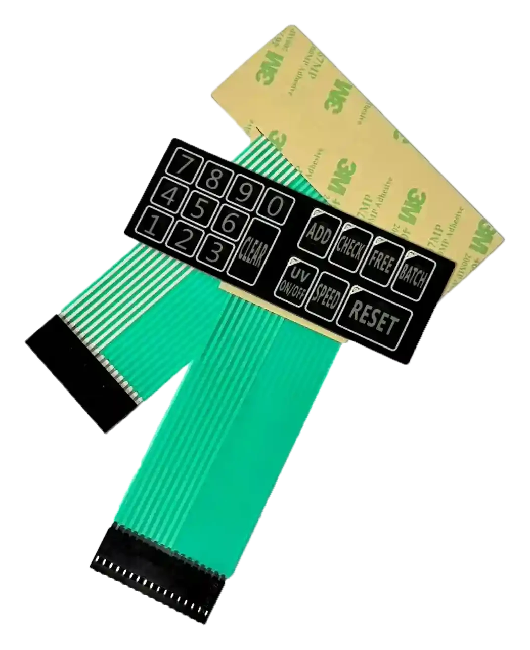
Obtain the exact mating connector identification and relevant manufacturer documentation. Check contact count and pitch alongside contact-side orientation, acceptable tail-end thickness, insertion geometry, retention features, and the required termination construction.
The Molex 200485 series datasheet is a useful example: it distinguishes connector orientation, contact position, grounding options, and FFC/FPC thickness requirements. It does not establish compatibility with an unidentified legacy tail or recommend that series as its replacement.
Use the membrane switch connector and tail guide to organize the interface review, then resolve the final requirements against the actual mating part.
Define the appearance and operating-feel reference
Specify legends, symbols, window positions, permitted cosmetic variation, tactile expectations, and visibility under relevant lighting. Identify whether the reference is approved artwork, an approved physical sample, or a newly agreed requirement.
Do not automatically reproduce discoloration, damaged printing, or the feel of a worn key. Where the original target cannot be verified, approve a new target explicitly rather than calling it an exact match.
4. Should you manufacture to print, seek functional equivalence, or redesign?
Choose the route according to the available evidence and permitted changes. The following are project-planning distinctions, not interchangeable guarantees of compatibility.
| Route | Suitable starting point | What the OEM must control |
|---|---|---|
| Build to print | A complete, authorized, released drawing package with usable material and component requirements | Compliance with the specified revision; any proposed substitution or deviation; required sample and production acceptance |
| Functionally equivalent replacement | Host and installation requirements can be established, but the original internal construction cannot or need not be reproduced exactly | A frozen external interface, measurable acceptance criteria, disclosed construction differences, and evidence that the candidate meets the approved requirements |
| Authorized redesign | The OEM permits changes to address obsolescence, failure history, assembly, usability, or new functions | The permitted change scope, affected hardware/firmware/housings, new documentation, and validation of the revised equipment configuration |
For a custom membrane keypad replacement, “same function” must be defined at the equipment level. A candidate that requires rewiring or different firmware is not interchangeable with an unchanged host merely because the same commands can eventually be produced.
Build-to-print work also needs review when a specified material or component is unavailable. Disclose the proposed difference instead of silently substituting it under the old specification.
Compare quotations against the same authorized route and deliverables. Separate documentation reconstruction, tooling, samples, validation responsibilities, and production supply so that a quotation based on assumptions is not compared with one based on a released package.
5. What belongs in the equivalence and difference matrix?
Record every requirement that must remain equivalent, every proposed change, and every unresolved item. The matrix should connect each entry to evidence, an impact assessment, a verification activity, and a responsible approver.
Illustrative example—not a JASPER customer case, approved design, or completed test record:
| Feature | Legacy evidence | Proposed candidate position | Evidence needed before approval |
|---|---|---|---|
| Key-to-pin mapping | An identified legacy circuit map is available | Preserve the map without changing host firmware | Independent mapping check and functional confirmation on the applicable host revision |
| Rear adhesive | Original grade is unknown | Specify a documented candidate material | Installation and bonding assessment on the actual surface, with relevant exposure checks |
| Tail-end support | A sample can be measured, but the original drawing is missing | Set the requirement from the identified mating interface | Dimensional inspection and mating/retention verification |
| Key feel | Only a field-used reference exists | Establish a newly approved assembled-key target | Agreed force/displacement assessment and application-specific usability review |
For a real project, add requirement IDs, old and new revisions, applicable limits, evidence references, owners, decisions, and unresolved actions. “Unknown” is not an equivalence result, and “proposed unchanged” is not evidence that a requirement has been met.
Assess the consequences beyond the switch itself:
Host electronics and firmware. Identify affected PCB, connector, harness, and software revisions. State which combinations the replacement will support and which require modification or separate approval.
Housing and assembly. Review changes to clearances, bonding areas, tail routing, fixtures, work instructions, and installation access. A change that leaves the front outline untouched may still require an assembly-process revision.
Product evaluation and documentation. Ask the responsible compliance and safety team whether changes to materials, labels, shielding, input behavior, or sealing affect existing evaluations or the supporting technical file. Record the review outcome and any required evidence; do not assume the previous product approval covers the new configuration.
Inventory and service. Identify existing stock, open orders, work in progress, service spares, and affected equipment revisions. Define whether old and new parts can be mixed, the effective production lot or serial range, and the disposition of stock that is not approved for the new configuration.
6. How should the replacement be validated?
Validate the proposed assembly against the approved equipment requirements. A successful power-on or a continuity check is not the complete acceptance plan.
Before testing, agree the sample quantities, configurations, procedures, acceptance limits, inspection stages, and responsible teams. Identify samples reserved for reference separately from those allocated to destructive or extended testing. Record the switch build revision, material traceability, host hardware, firmware, housing, test equipment, and test conditions.
| Validation area | What to examine | Basis for acceptance |
|---|---|---|
| Installation and mechanical fit | Positioning, windows, clearances, tail routing, connector access, assembly handling | Approved drawings and installation requirements for the relevant housing variants |
| Electrical and host function | Key mapping, released states, press/hold/release behavior, required combinations, indicators and startup behavior | Approved circuit requirements and expected behavior on the supported host configurations |
| Appearance and operating feel | Legends, symbols, alignment, windows, finish, key response and application-specific operation | Approved artwork, appearance references, and agreed assembled-key criteria |
| Bonding and sealing, where required | Bonding surface, adhesive footprint, edges, tail entry, housing interfaces | Agreed installation and sealing requirements evaluated in the intended assembly |
| Environmental and cleaning exposure | Relevant temperature, humidity, cleaning agents, moisture, sunlight, vibration or storage conditions | A project-specific exposure profile, with defined functional and physical checks |
| Actuation durability | Repeated operation under the agreed loading and electrical conditions | Defined cycle target, monitoring criteria, and permitted changes in function and physical condition |
| Production readiness | First production output, revision identification, inspection records, packaging and handling | The released specification, approved deviations, and agreed production controls |
ASTM F1578-24 specifically addresses contact-closure cycling of membrane switches. Its public scope covers repeated depression and release to a predetermined cycle count, including optional specified electrical loading. Use the applicable method and project requirements to define the test; a component rating alone does not establish the replacement assembly’s demonstrated life.
IEC 60068-1:2013 provides an environmental-testing framework that includes tailoring tests and severities to expected transport, storage, and operating conditions. Name the relevant conditions rather than specifying an undefined “standard environmental test.”
For cycling, document the actuation setup, loading, rate, electrical conditions, monitoring intervals, and failure criteria. For cleaning, identify the agent, concentration, application method, frequency, and evaluation criteria. Select the values from the project—not from an unrelated sample report or a generic industry maximum.
Review relevant function and physical condition before, during, and after exposure as required by the protocol. A change introduced after testing needs an assessment of which evidence remains applicable and which checks must be repeated.
7. What should an OEM send with the replacement RFQ?
Send a replacement-specific package alongside the membrane switch RFQ checklist. The package should make the missing information and permitted changes visible, not conceal them behind “please copy this sample.”
Legacy evidence and authorization: old part numbers and revisions; available drawings and artwork; front, rear, tail and interface photographs; sample identities and condition; permission to use the supplied material; and any restrictions on destructive inspection or disclosure.
Equipment and acceptance requirements: housing information, mating connector documentation, verified circuit or pinout information, supported hardware and firmware revisions, key functions, operating and cleaning conditions, failure history, unchanged interfaces, and authorized redesign options.
Supply and approval planning: evaluation quantity, initial order and expected continuing demand, service-support needs, remaining approved stock, requested delivery dates, validation responsibilities, required records, and the people authorized to approve changes.
Label a requested date as a project need rather than an assumed supplier commitment. Ask the quotation to identify assumptions, excluded work, and the information still required before final pricing, tooling, or production release.
8. What must be signed before production or service release?
Release a controlled replacement configuration, not an isolated sample. The approval should identify the drawings, artwork, circuit map, material specification, applicable equipment revisions, validation evidence, and accepted differences that define the part.
Use the following as a blank change-release worksheet. Complete it from project records; no approval or test result is implied.
| Record field | Entry to complete |
|---|---|
| Change identity | Change request ID: ____; reason: ____; old part/revision: ____; replacement part/revision: ____ |
| Applicable equipment | Host hardware: ____; firmware: ____; housing revision: ____; supported configurations: ____ |
| Controlled build package | Drawing: ____; artwork: ____; circuit/pinout: ____; material/BOM revision: ____; assembly instruction: ____ |
| Differences and evidence | Difference-matrix revision: ____; validation report IDs: ____; reference sample IDs: ____; accepted deviation IDs and limits: ____ |
| Open-action disposition | Remaining actions: ____; responsible owners: ____; release restrictions or closure evidence: ____ |
| Approval decision | Approve / hold / reject: ____; engineering: ____; quality: ____; manufacturing/service: ____; purchasing: ____; compliance, where applicable: ____; dates: ____ |
| Implementation and stock | Effective lot or serial range: ____; old-stock disposition: ____; mixed-stock rules: ____; service instructions: ____ |
Do not use a temporary deviation as an undocumented permanent specification. State its scope and expiry or closure condition. Define the change-notification and reapproval process for later material, construction, artwork, or interface changes.
Start an authorized OEM replacement inquiry
Send JASPER clear photographs of the old switch’s front, rear, tail termination, and mating interface, together with dimensions, key functions, operating conditions, cleaning exposure, available documents, and required quantities.
State what must remain unchanged and what your team authorizes for redesign. Describe any unresolved information and confirm permission to share the supplied material.
Submit an OEM replacement inquiry.
A photo-based inquiry starts a project assessment. It does not establish full compatibility, original-manufacturer authorization, availability of a third-party spare part, or approval for use in the equipment.
Ready to Start Your Project?
Tell us about your membrane switch, keypad, or graphic overlay requirements. Our engineering team will review your specifications and provide a detailed quote.