A useful PCB assembly surface finish comparison starts with assembly geometry, time before soldering, and the function of exposed contacts. Shortlist a flat finish for fine-pitch or hidden-joint packages, then verify its compatibility with the actual storage and soldering sequence. Consider ENIG for general fine-pitch assemblies, lead-free HASL where pad topography is acceptable, and OSP, immersion silver or immersion tin where their handling requirements fit the build. Evaluate ENEPIG when soldering and wire bonding share a substrate. Specify repeatedly mated contacts separately.
- Choose a Surface Finish Around Assembly and End Use
- What the Wrong Finish Can Cost
- Compare Planarity for Fine-Pitch and Hidden-Joint Packages
- Review Storage, Handling and Multiple Thermal Exposures
- Protect the surface that will actually be joined
- Review the complete thermal route
- Separate Solderable Surfaces from Contact-Surface Requirements
- Match Finish Verification to the Selected Board Supply
- Read thickness values with their source and purpose
- Distinguish deposition evidence from assembly evidence
- A Finish-Selection Matrix for Different Build Conditions
- Ten Criteria for Approving a Surface Finish
- A Six-Step Finish Review and Procurement Handoff
- Step 1 — Map surface functions
- Step 2 — Document the build history
- Step 3 — Obtain comparable proposals
- Step 4 — Agree qualification and acceptance
- Step 5 — Release the selected construction
- Step 6 — Control repeat orders and exceptions
- Eight Reasons to Reject or Escalate a Finish Proposal
- Prepare the Next Build Review
Choose a Surface Finish Around Assembly and End Use
A PCB surface finish protects exposed copper and provides the interface needed for a later joining or contact operation. The right choice is therefore a board-specific decision, not a ranking from cheapest to most expensive. A finish suitable for solder pads may be unsuitable for a connector that must withstand repeated insertion.
The six principal assembly options in this guide are electroless nickel immersion gold (ENIG), lead-free hot air solder leveling (HASL), organic solderability preservative (OSP), immersion silver, immersion tin, and electroless nickel electroless palladium immersion gold (ENEPIG). Selective hard gold is the additional contact-surface option. These names describe different finish systems, not interchangeable quality grades.
Start the review with the most restrictive feature. A fine-pitch land pattern makes pad uniformity important. A connector creates a separate mechanical and electrical interface. A long gap between fabrication and assembly makes preservation evidence important. Where several constraints coexist, consider selective finishes rather than forcing every exposed feature to use the same treatment.
Ask the fabricator to quote the actual board construction and finish zones. Ask the assembler to review the proposed finish against component attachment requirements. The OEM should own the final decision, including any exception to the released drawing. A supplier’s preferred process is useful information, but it is not a substitute for application requirements.
What the Wrong Finish Can Cost
An unsuitable finish can move cost from the bare-board purchase into assembly troubleshooting, inventory disposition or field-contact problems. Evaluate the cost of an accepted assembly, not the surface-treatment line item alone. Uneven attachment surfaces can affect printing and soldering; a finish chosen for solderability does not automatically provide adequate mating durability.
Consider a repeat-order scenario: the board outline and copper artwork remain unchanged, but purchasing accepts a different finish to improve availability. The substitution still needs engineering review. Pad topography, storage controls, the soldering route and any exposed contacts must be checked before the cheaper board is treated as equivalent.
A useful quotation comparison includes board price, selective-processing charges, packaging, incoming verification, assembly qualification, and the consequence of unusable inventory. Separate one-time qualification expense from recurring build expense. Do not assign a universal cost premium to ENIG or ENEPIG: obtain comparable quotations for the same design, quantity and evidence package.
The practical objective is to remove unsupported substitutions before components are loaded. A written review at procurement is easier to manage than an unresolved finish question after an expensive assembly has been built.
Compare Planarity for Fine-Pitch and Hidden-Joint Packages
Surface-finish planarity matters when the attachment process needs a uniform printing and seating surface. Documented QFN and SON assembly guidance calls for a flat, uniform attachment site and recognizes more than one acceptable finish. Select by package and process rather than declaring ENIG mandatory for every leadless device.
Lead-free HASL deserves a specific topography review because solder coating height can vary across pads. For a design with small lands or hidden joints, compare the actual finish profile with the package’s attachment guidance and the assembler’s printing process. Do not turn one supplier’s pitch recommendation into a universal cutoff for every package.
Immersion silver provides another flat, nickel-free soldering surface, and OSP can support lead-free assembly when its chemistry and process are suitable. Neither choice removes the need to examine copper geometry, board flatness, solder-mask openings or solder-paste deposition. A finish decision addresses only part of the attachment system.
For approval, request evidence from representative pads, not just a photograph of an easy-to-measure coupon. Agree which package families govern the decision and what the first build must demonstrate. A good signal is a documented printing and attachment review. A red flag is the claim that a flat finish alone guarantees acceptable hidden joints.
Review Storage, Handling and Multiple Thermal Exposures
Surface-finish storage suitability depends on the supplied chemistry, packaging and exposure history. A published shelf-life figure is a planning input, not proof that an individual lot remains solderable. Keep sealed storage life, time after opening, and time between assembly operations as separate controls.
For purchase planning, require a finish date or traceable lot date, the supplier’s sealed-pack storage limit, temperature and humidity requirements, permitted packaging materials, and instructions for partly used packs. Ask when the stated storage period starts. Shipment date and finish-application date should not be silently treated as the same event.
The public IPC-4553A scope describes a 12-month immersion-silver shelf-life capability under specified handling; the referenced supplier’s commercial comparison lists six months. Treat that difference as a question for the supplying fabricator, not as an automatic extension. The order needs a supplier-agreed limit for its own process and packaging.
Use the latest planned soldering date, not only the receiving date, in the comparison. A lot within its agreed storage period on arrival can still fall outside that window before the final operation. Split deliveries or smaller packs may resolve this mismatch without changing the finish.
Protect the surface that will actually be joined
Immersion silver requires protection from handling contamination and sulfur exposure; unprotected silver can react with sulfur to form surface sulfide. OSP also needs handling controls, including avoiding damage to the protective film. Define whether the supplier’s packaging remains suitable after opening and who is responsible for resealing unused boards.
Do not treat discoloration as a complete diagnosis. When the lot history or surface condition is questionable, have quality engineering determine the applicable inspection and solderability evidence before release. A visual observation should lead to a defined disposition, not automatic acceptance or automatic scrapping of every board with the same appearance.
Review the complete thermal route
Map each exposure before the relevant surface receives its final joint: first-side reflow, second-side reflow, later connector soldering, and permitted local rework. Include waiting periods and any proposed baking or cleaning operation. For example, a double-sided assembly followed by selective soldering requires evaluation of pads and holes that remain unsoldered through earlier heating.
Do not impose a universal two-reflow limit on OSP. High-temperature OSP products are available for multiple heat cycles. Their suitability still depends on the selected product and actual assembly conditions, not the acronym alone. Likewise, immersion tin requires attention to tin-copper intermetallic growth and remaining solderable tin; total coating thickness does not tell the whole aging story.
Baking must be a jointly approved moisture-control action, not a presumed way to reset finish life. The referenced supplier flags adverse baking effects for OSP and immersion tin. The release decision should address both laminate moisture requirements and the solderability of the finish after the proposed treatment.
Separate Solderable Surfaces from Contact-Surface Requirements
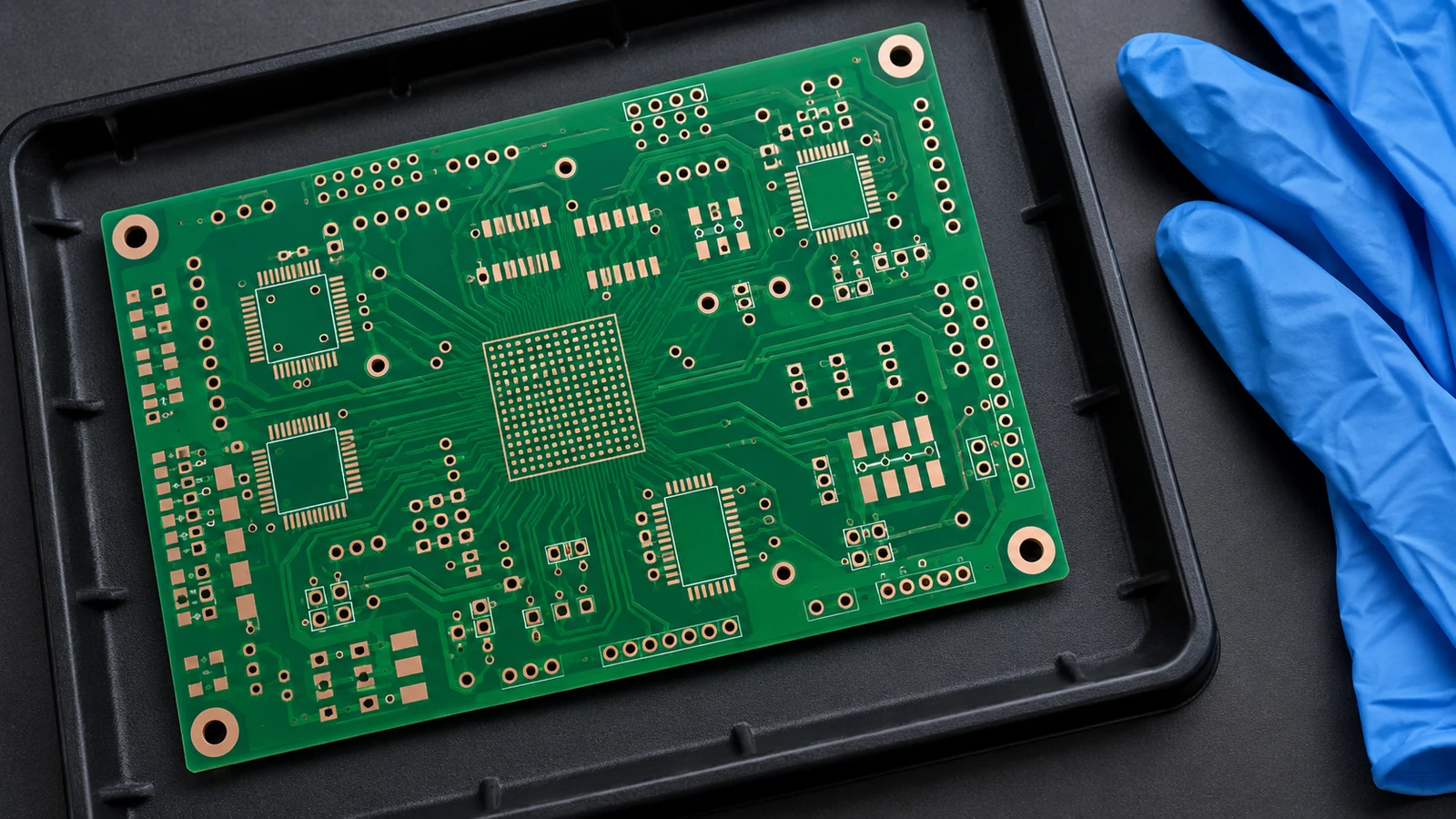
Solder pads and functional contacts should share a finish only when both uses are qualified. Soldering, wire bonding, probe contact and repeated mechanical mating create different acceptance questions. A single drawing note reading “gold finish” does not define those interfaces adequately.
For edge connectors, selective hard gold over nickel is the relevant starting point for repeated insertion and withdrawal. The referenced supplier explicitly distinguishes this construction for repeatedly plugged connectors. Specify the mating system, plating zone, deposit requirements, contact force and intended durability. Do not equate the thin immersion-gold layer of ENIG with a wear-rated hard-gold contact system.
For wire bonding, ENEPIG is a candidate because it supports soldering and qualified wire-bond applications. Confirm the wire material, bonding method, cleaning sequence, storage interval and bond-test requirements with the bonding supplier. The word “bondable” is not permission to substitute any gold-colored finish or to accept an untested process change.
For press-fit connectors, confirm the permitted board finish together with finished-hole geometry and the connector supplier’s installation requirements. Immersion tin has press-fit uses, but a solderability specification alone does not qualify a press-fit interface. Where exposed tin remains in service, include whisker requirements in the supplier review rather than treating solderability approval as the whole reliability assessment.
For dome, spring or elastomer contacts, identify the counterface material, force, motion, environment and resistance limit before selecting the finish. Treat these as contact-design inputs, not as evidence that selective hard gold is automatically necessary everywhere. Keep solder out of designated contact zones unless the contact design expressly requires it.
A selective solution is often worth reviewing. OSP chemistry is available for boards with copper and selective gold areas. That establishes a possible process route, not universal compatibility between every OSP product and every gold process. Obtain a defined finish map and agreement on the sequence used by the selected fabricator.
Match Finish Verification to the Selected Board Supply
Finish verification must connect the drawing, the supplying process and the received lot. Specify the finish system and contractually applicable standard revision, then request evidence appropriate to its function. Public supplier ranges are useful for screening quotations, but they do not replace a controlled acceptance specification.
Read thickness values with their source and purpose
The following values are reference inputs for a supplier discussion. The metallic examples come from a published finish comparison; the OSP value is specific to the F2(LX) formulation. They are published examples, not a combined IPC acceptance table or contractual tolerances for an order. Where these examples differ from the contracted standard edition or supplier-agreed limits, the released purchase specification controls. Do not combine limits from different editions into a new acceptance range.
| Surface finish | Published thickness reference, µm | What the order must resolve |
|---|---|---|
| ENIG | Nickel 3–6; gold 0.05–0.125 | Governing IPC-4552 revision, deposit measurement and corrosion evaluation |
| Lead-free HASL | 1–40 | Solder alloy, coating coverage and pad topography; not a precision coplanarity tolerance |
| OSP | 0.15–0.30 for F2(LX) | Exact chemistry and supplier-approved film control; use the applicable high-temperature OSP specification |
| Immersion silver | 0.12–0.40 | Governing IPC-4553 revision, coverage and packaging requirements |
| Immersion tin | At least 1.0 | Governing IPC-4554 revision; measurement basis and remaining solderable tin after the relevant history |
| ENEPIG | Nickel 3–6; palladium 0.05–0.30; gold 0.05–0.125 | Governing IPC-4556 revision and amendments; separately controlled layers and joining requirements |
| Selective hard gold | Defined by the contact specification | Gold and nickel deposits, hardness, plating zone and mating qualification |
Thickness is a continuous process variable, not a menu of performance grades. Do not round a supplier’s available process into an invented standard value. For the cited OSP chemistry, both insufficient and excessive film thickness can be undesirable; thicker is not automatically safer.
Distinguish deposition evidence from assembly evidence
For ENIG and ENEPIG, ask how deposit measurements represent the supplied lot. An X-ray fluorescence (XRF) report should identify the measured layer stack, measurement locations and applicable calibration. Measurement capability matters. A thickness result does not, by itself, establish deposit integrity or joint reliability; require any corrosion assessment called for by the released specification.
Use the IPC-4552, IPC-4553, IPC-4554 and IPC-4556 families for the corresponding metallic finishes, with the exact contractual revisions recorded. IPC-4555 addresses high-temperature OSP. J-STD-003 addresses printed-board solderability; it is not a finished-assembly acceptance certificate.
Agree the solderability method, specimen, conditioning, sampling and acceptance criteria before an exception occurs. A generic certificate cannot answer an application-specific question that was never specified. Keep supplier declarations, actual lot measurements and assembly-trial observations identifiable as different evidence types.
A Finish-Selection Matrix for Different Build Conditions
A finish-selection matrix should narrow candidates while exposing the question that can disqualify each one. The following matrix combines the preceding material considerations with proposed procurement checks; it does not approve a finish independently of the actual board and process.
| Surface Finish | Assembly Consideration | Storage and Handling | Contact-Use Question | Verification Needed |
|---|---|---|---|---|
| ENIG | Flat candidate for fine-pitch soldering | Record supplier limits and protect from contamination | Is this a solder pad, static contact or wear interface? | Layer measurements, corrosion controls and relevant assembly evidence |
| Lead-free HASL | Review coating topography on small lands | Follow supplied packing and storage instructions | Is a solder-coated surface permitted at the interface? | Alloy identity, coverage and attachment review |
| OSP | Qualify chemistry for the complete lead-free route | Protect film; control opening, waiting and cleaning | Will the feature be soldered, or must exposed copper act as a contact? | Product identity, film control and post-history solderability |
| Immersion silver | Flat, nickel-free soldering candidate | Control handling and sulfur exposure | Does the contact environment suit the selected silver system? | Coverage, packaging and application-specific exposure evidence |
| Immersion tin | Assess the unsoldered surface after prior heating | Record age, storage and any proposed bake | Does the press-fit supplier approve the interface? | Thickness basis, remaining solderable tin and connector requirements |
| ENEPIG | Candidate for combined soldering and wire bonding | Protect bond surfaces and track exposure history | Which bonding process or contact duty is required? | Layer controls, soldering evidence and bond qualification |
| Selective hard gold | Confine to defined contact zones | Protect against abrasion and contamination | What mating duty must the contact withstand? | Plating-zone inspection and mechanical/electrical contact qualification |
Translate that comparison into the intended build rather than selecting from appearance or nominal price alone.
| Build condition | Candidate starting point | Release condition |
|---|---|---|
| Fine-pitch controller with hidden joints | ENIG; compare qualified OSP or immersion silver | Representative printing and joint formation meet the agreed requirements |
| Conventional mixed-technology board with tolerant land geometry | Lead-free HASL | Actual pad profile, solder alloy and assembly route are acceptable |
| Fast-moving production with controlled work-in-process | High-temperature OSP | Selected chemistry survives the planned handling, waiting and heating sequence |
| RF assembly with exposed finished conductors | Immersion silver among the candidates | Electrical designer accepts the actual finish stack and environmental controls |
| Board with press-fit connectors | Immersion tin where connector requirements allow | Connector-specific hole, finish and installation requirements are satisfied |
| Substrate combining soldered parts and wire bonds | ENEPIG | Both joining processes are qualified on the proposed supply |
| Serviceable edge connector | Selective hard gold with a separate solder-pad finish | Contact duty and all finish-zone boundaries are released |
The RF row is a screening suggestion, not a universal frequency threshold. Immersion silver is a documented option for high-frequency applications, but the circuit designer must determine relevance to the actual exposed conductors.
Ten Criteria for Approving a Surface Finish
An OEM finish review should leave a written answer to each criterion below. These checks translate the comparison into release evidence. A good signal supports approval; a red flag identifies a question to resolve rather than an automatic failure of every board using that finish.
| Evaluation criterion | Good signal | Red flag |
|---|---|---|
| 1. Package attachment | Package guidance and representative pads reviewed | Selection based only on board size or appearance |
| 2. Printing and seating | Actual pad topography considered with the print process | Flatness assumed to guarantee good joints |
| 3. Alloy and flux compatibility | Materials and joining route identified | Finish approved independently of assembly materials |
| 4. Unopened storage | Supplier conditions and traceable dates recorded | Shelf life quoted without its starting point |
| 5. Open-pack handling | Defined protection, resealing and waiting controls | Part-used packs returned without exposure history |
| 6. Thermal sequence | Unsoldered pads evaluated after preceding operations | Approval based only on the first reflow |
| 7. Contact function | Mating, bonding, probing or press-fit duty specified | All exposed features called “gold contacts” |
| 8. Finish evidence | Layer, coverage and applicable process records linked to the lot | A generic certificate presented as every required test |
| 9. Changes and alternatives | Supplier, chemistry and finish changes require review | “Equivalent finish” substitution without approval |
| 10. Total procurement cost | Qualification, preservation and usable inventory considered | Decision based exclusively on bare-board unit price |
Use mandatory requirements as gates, not as points that can be offset by a lower quotation. For example, satisfactory packaging cannot compensate for an unqualified mating interface. When two candidates meet all gates, compare total cost and supply practicality on equal terms.
A Six-Step Finish Review and Procurement Handoff
A surface-finish approval should travel with the manufacturing release package. The following six-step handoff assigns decisions before quotation acceptance and preserves the evidence needed for repeat orders.
Step 1 — Map surface functions
The design engineer identifies solder lands, bonding pads, test points, press-fit holes and functional contacts. The output is a finish-zone drawing with the controlling component or connector requirements. Resolve ambiguous features before asking a supplier to price them.
Step 2 — Document the build history
The manufacturing engineer records assembly order, expected storage, waiting periods, cleaning and permitted rework. Identify which features remain unsoldered at each stage. The output is a route against which every proposed finish can be evaluated consistently.
Step 3 — Obtain comparable proposals
Purchasing requests named finishes, supplying sites, applicable specification revisions, packaging conditions and included verification. Separate any selective finish from the general solder-pad finish. The output is a quotation comparison without hidden differences in scope.
Step 4 — Agree qualification and acceptance
Quality and manufacturing engineering define the trial, specimens, lot records and application tests. Distinguish solderability evidence from completed-joint inspection and contact qualification. The output is an approval plan with named owners and explicit release criteria.
Step 5 — Release the selected construction
The OEM approves the finish and records the decision in the drawing, purchase specification and assembly documentation. Identify any restrictions on storage or process changes. The output is one consistent configuration rather than conflicting drawing and quotation notes.
Step 6 — Control repeat orders and exceptions
Receiving verifies lot identity and the required records. Engineering reviews changes to supplier, chemistry, finish stack, packaging or assembly history. The output is a traceable release or disposition; a repeat part number alone does not approve a changed finish.
Eight Reasons to Reject or Escalate a Finish Proposal
Escalate a surface-finish proposal when its evidence cannot support the intended build. Place the affected approval or lot on hold while the responsible owner resolves the specific issue; escalation does not necessarily mean changing to a more expensive finish.
- The drawing, quotation and board order name different finishes, alloys or selective plating zones.
- A fine-pitch package lacks a credible pad-topography and attachment review.
- Storage history, package integrity or finish-date traceability is insufficient for the planned release.
- A supplier recommends baking, cleaning or additional heating without assessing finish compatibility.
- A wear contact is substituted with immersion gold without contact-system qualification.
- Required measurements cannot be connected to the supplied lot or identified measurement locations.
- Wire-bond or press-fit suitability is inferred solely from a solderability claim.
- A repeat-order substitution changes the finish or its supplying process without the OEM’s approval.
Reject the proposal when a mandatory application requirement cannot be met. Where the missing item is evidence rather than demonstrated incompatibility, request a defined investigation or trial. Do not convert uncertainty into either a blanket acceptance or an unsupported claim that one finish family is defective.
Frequently Asked Questions
PCB surface-finish decisions become clearer when package, preservation and contact requirements are kept distinct. The following answers apply the selection and verification approach above to common OEM purchasing questions.
Which surface-finish factors matter most for PCB assembly?
The most important factors are pad uniformity, compatibility with the soldering process, preservation before assembly, thermal history and the function of exposed contacts. Review them against the actual packages and manufacturing route. The preferred finish is the one supported by the required application evidence, not simply the most expensive option.
Does the flattest finish always make the best procurement choice?
No. Flatness is valuable for fine-pitch attachment, but it does not establish storage suitability, wire bondability, contact durability or supply practicality. Compare candidates that meet the package requirements, then check handling, process compatibility and total procurement cost. A flat surface is one qualification input, not a complete approval.
Should contact pads and solder pads use the same finish?
Only when the selected finish is qualified for both functions. Repeatedly mated edge contacts, wire-bond pads, press-fit holes and solder lands have different requirements. A selective finish can separate these functions. Define the contact duty and finish boundaries on the drawing instead of assuming all gold-colored surfaces are equivalent.
How does repeated thermal exposure affect finish selection?
Repeated thermal exposure makes the condition of surfaces awaiting soldering especially important. Assess the complete sequence, including waiting periods and any rework or baking. Do not impose one cycle limit on an entire finish family. Obtain evidence for the selected chemistry, board construction and assembly route under the intended conditions.
What should an OEM confirm before changing the finish on a repeat order?
An OEM should confirm the revised finish specification, supplying process, package compatibility, storage controls, contact requirements and necessary requalification. Update the drawing and purchase documentation before release. Unchanged copper artwork does not make a finish substitution automatically equivalent, particularly when contacts or later soldering operations remain part of the build.
Is ENEPIG automatically better than ENIG?
No. ENEPIG is worth evaluating when soldering and wire bonding must share a substrate, but that does not make it necessary for every solder-only board. Assess the actual joining requirements, supplier process control and qualification effort. Additional layers do not remove the need for application-specific evidence and acceptance criteria.
Can an expired or poorly stored PCB lot be rescued by baking?
Baking is not an automatic remedy for finish aging or contamination. It may be appropriate for moisture management only when the board and finish requirements permit it. Obtain an approved disposition based on the storage history and relevant testing. Do not reset shelf life merely because a bake was completed.
What finish thickness should be written on the purchase order?
Specify the selected finish system, applicable standard revision and supplier-agreed deposit requirements rather than copying a generic comparison range. Identify the relevant layers, measurement basis and acceptance evidence. For selective contacts, include the contact-specific deposit requirements. For OSP, name the chemistry and its qualified film-control requirements as well.
Which records should accompany the first order?
Request the released finish specification, supplying-site and lot identification, storage and packaging instructions, and the agreed inspection or measurement records. Include solderability, assembly-trial, bond or contact evidence where the application requires it. Keep each record linked to its purpose so a supplier declaration is not mistaken for a completed qualification.
Prepare the Next Build Review
For the next PCB assembly surface finish comparison, prepare the fabrication drawing, component list, critical package guidance, assembly sequence, expected storage period and contact-use details. Mark all selective finish zones and identify any proposed change from an earlier build.
Use JASPER’s PCB assembly services as the starting point for discussing the board and assembly requirements. Request a finish proposal tied to the actual design and supply conditions, with agreed verification and change controls. Release the order when the design, purchasing and assembly documents describe the same approved construction.
Ready to Start Your Project?
Tell us about your membrane switch, keypad, or graphic overlay requirements. Our engineering team will review your specifications and provide a detailed quote.