The PCB assembly process converts released design files and accepted materials into populated, inspected and tested circuit boards, followed by a documented shipment release. For serialized OEM builds, use a 100% record-coverage target: every shipped board links to its approved configuration and required inspection and test results. That target measures traceability, not complete defect detection. A useful production plan therefore names the owner, input and release evidence at each handoff. It also separates actual processing from time spent waiting for components, engineering decisions, fixtures or customer approval.
- Read the Process as a Series of Release Gates
- Release Files and Freeze the Build Baseline
- Receive Boards and Components Against the Kit
- Print, Place and Reflow Surface-Mount Parts
- Approve the setup before repeating it
- Insert and Solder Through-Hole Components
- Inspect, Program and Test the Assembled Boards
- Control the firmware and test interfaces
- Release Shipment Records and Close Build Exceptions
- Compare the Assembly Routes
- Specify Standards, Interfaces and Record Coverage
- Separate Processing Time from Waiting Time
- Apply the Gates to Five OEM Build Scenarios
- Prepare the Next Build Review
Read the Process as a Series of Release Gates
A PCB assembly release gate is the decision that a defined set of boards, materials or files is ready for the next operation. The production traveler, whether electronic or paper, records the route and completion evidence. Passing one station does not authorize every later activity.
- Released files and build baseline
- Accepted boards, components and tooling
- Approved mounting route
SMT-only or mixed technology: → Apply paste, inspect deposits and place SMT parts
- Apply paste, inspect deposits and place SMT parts
- Approve first-board setup, reflow and inspect
Separate through-hole operation: → Insert and solder through-hole parts
No separate through-hole operation: → Complete specified inspection, programming and tests
- Insert and solder through-hole parts
- Complete specified inspection, programming and tests
- Required evidence and dispositions complete?
Yes: → Authorize shipment records and protective packaging
No: → Hold affected boards, resolve exceptions and repeat affected checks
- Authorize shipment records and protective packaging
- Hold affected boards, resolve exceptions and repeat affected checks
Approved pin-in-paste parts can share a reflow operation. Customer first-article holds, cleaning, coating and depanelization belong at their agreed positions in the traveler; the diagram shows the main handoffs.
| Process Gate | Required Input | Responsible Function | Release Evidence | Next Handoff |
|---|---|---|---|---|
| Engineering release | Matched PCB data, BOM, placement file, drawings and acceptance plan | OEM engineering; assembler manufacturing engineering | Approved release manifest and resolved build questions | Procurement, tooling and production planning |
| Material readiness | Released BOM, received boards/components and handling requirements | Materials team and incoming quality | Accepted kit, shortage disposition and material identity records | Line setup and assembly |
| SMT assembly | Accepted kit, paste/stencil data and placement program | SMT production, process engineering and quality | Setup approval, first-board checks and specified solder/placement inspection | Through-hole operations or verification |
| Through-hole completion | Insertion drawing, approved soldering route and completed preceding operations | Assembly production and quality | Insertion, joint and mechanical checks; recorded disposition | Final inspection and test |
| Verification | Correct assembly revision, firmware, fixtures and test limits | Test engineering and quality | Required inspection, programming and test records; cleared failures | Shipment release review |
| Shipment | Accepted boards, quantity reconciliation and required documents | Quality release authority and logistics | Authorized release, board identification and packing record | OEM receiving or integration |
Assign actual approvers before work starts. Any gate can hold affected material; a production schedule cannot override an unresolved technical disposition.
Release Files and Freeze the Build Baseline
Engineering release starts the controlled PCB assembly workflow when the OEM authorizes a build package and the assembler accepts it for the specified quantity and configuration. A quotation upload alone does not establish that baseline. Procurement and tooling may start earlier under separate authorization.
Release the PCB fabrication data, bill of materials (BOM), component placement list (CPL), assembly drawings and inspection/test requirements together. Include firmware and configuration data when programming is ordered. Eurocircuits’ assembly data guidance identifies BOM and CPL consistency as a prerequisite for production preparation.
The files need compatible revisions, not necessarily identical revision letters. For example, one release manifest can pair PCB revision C, BOM revision E, assembly variant A and firmware v2.4.1. That is one authorized combination. Keep superseded files distinguishable from the active package.
For placement data, specify coordinate units, origin, rotation convention and board side. A mirrored bottom-side interpretation can put the correct part in the wrong orientation. For the BOM, identify manufacturer part numbers, reference designators, quantities, approved substitutes and do-not-populate (DNP) positions.
Close manufacturing questions before the affected operation. Missing polarity information needs an engineering answer; it should not become an operator’s guess. Define who can approve substitutions and whether a customer first article is required before the remaining quantity proceeds.
Freeze the baseline through change control. An engineering change order (ECO) should identify affected boards, material and tooling, the new effective revision, and whether work already in progress must stop or be reworked. A revised attachment without an effective boundary is insufficient.
Receive Boards and Components Against the Kit
Material readiness means the required boards and components are accepted, identifiable and available for the authorized build. Arrival is only receipt. Incoming quality must establish whether that material can enter usable stock before the materials team releases it to the production kit.
Start with identity. Reconcile PCB revision, manufacturer part numbers, quantities, packaging condition and the specified lot/date-code records against the released BOM and the material actually delivered to receiving. Check setup allowances separately. A universal attrition percentage cannot represent every package and batch size.
Check moisture-sensitive device status before issuing parts. Opening time and exposure history matter. Texas Instruments’ packaging guidance connects component storage suitability to packaging, moisture sensitivity and storage conditions, so receiving and production need the applicable handling instructions before deciding whether a device is ready for reflow. Avoid a universal bake cycle.
Missing-component checks belong at several points: BOM review establishes what should be fitted, kit reconciliation establishes what is available, and assembly inspection establishes what reached the board. A DNP position is intentional only when the released variant says so.
Put shortages on a controlled list with an owner and disposition. A partial build needs explicit authorization covering omitted positions, identification and the later completion/test route. Material ownership under turnkey or consigned supply changes who resolves a shortage; it does not remove the readiness check.
Print, Place and Reflow Surface-Mount Parts
SMT assembly applies solder paste, places surface-mount components and reflows the populated board under an approved process. Release to the next operation depends on setup and inspection evidence, not simply on completion of the placement program.
Paste application can use stencil printing or jet dispensing, selected for the board and production route. Solder paste inspection (SPI), when specified, checks deposit characteristics before placement. The placement setup then aligns the board using its references and maps each feeder or tray to the correct BOM item. Eurocircuits describes these stages in its assembly process overview.
Approve the setup before repeating it
The first populated board or panel should confirm component identity, fitted/DNP positions, orientation and placement against the released data before the batch repeats the setup. For example, check U1 pin 1 against the drawing and J4’s fitted status against the BOM variant. First-board inspection can catch setup errors before reflow. Record the checked configuration, findings, corrections and authorized continuation.
Reflow melts the solder and then allows the joints to solidify. The approved thermal process must suit the actual assembly, paste and component limits. It cannot be reduced to one temperature or dwell time for every board. Inspect the soldered result using the specified criteria and access methods.
Customer first-article approval is a separate hold. It may require completed, programmed and tested samples before the rest of the batch is authorized; CircuitHub’s first-article explanation distinguishes that request from routine internal checks. Agree the sample quantity, evidence, approver and response window in advance.
For double-sided SMT, define side order, support and thermal exposure before setup. Approve any changed program or process through the applicable release check.
Insert and Solder Through-Hole Components
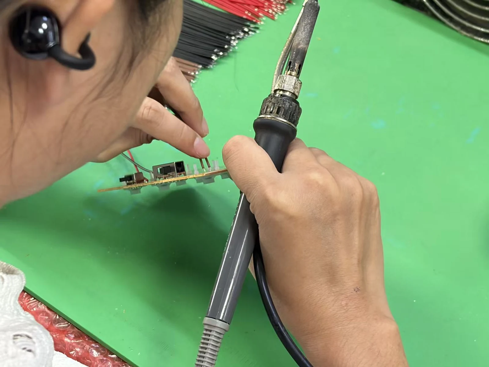
Through-hole completion installs and solders the leaded components specified by the BOM and drawing. An SMT-only board skips this operation. A mixed assembly follows the approved sequence so later soldering does not compromise earlier work.
Conventional options include wave soldering, selective soldering and hand soldering. Choice depends on joint access, component compatibility, quantities and tooling. A selective nozzle must reach its target without damaging adjacent parts; wave processing requires a suitable board configuration and protection where needed. Eurocircuits’ selective soldering guide illustrates the access considerations.
Pin-in-paste reflow is another option for compatible through-hole parts. It can combine their soldering with a reflow step, but the connector body, hole/lead geometry and paste provision must support that route. Samtec’s processing guidance explains these eligibility conditions.
Before release, check insertion height, polarity, connector orientation, joint condition and mechanical retention against the drawing. Include separately fitted hardware. A connector’s electrical pins and mechanical fixing points can require different completion checks, so both must be covered when specified. Record unfinished operations in the traveler. An SMT pass cannot release an incomplete connector to final acceptance.
Inspect, Program and Test the Assembled Boards
Verification releases a PCBA against its agreed inspection and test plan. Configuration matters. The purchase order must identify the evidence required for each board or lot, including how the inspection disposition, programmed image and electrical results connect to the released hardware variant.
Automated optical inspection (AOI) assesses accessible assembly features within the inspection program’s coverage; X-ray can assess selected hidden-joint features. In-circuit test (ICT), flying probe and functional test address defined electrical checks through suitable access and equipment. Define the limits. A list of method names does not explain which connections or operating functions the test plan covers.
Control the firmware and test interfaces
Load firmware before its dependent tests. Programming may occur before placement, on an assembled board or within a test station, provided the route controls the image and configuration and preserves the required checks before power is applied. Verify the shipping image. A diagnostic image used earlier does not establish the final configuration.
Specify programming-interface pinout, target voltage, image version or checksum, device configuration and serial-specific data. Keep the test procedure under revision control. Its fixture identity, inputs, loads, limits and result format must be clear enough for test engineering to reproduce the acceptance decision for the actual board variant.
For serialized builds, apply the 100% record-coverage target to the shipment list. Every shipped serial needs its required inspection disposition and test results; a test omitted by mistake cannot be treated as a pass.
Failed boards move to controlled disposition. Preserve the original failure, approved corrective work and the required reinspection/retest evidence. Repeating a test until a board passes, without addressing the cause or documenting a valid test-system correction, leaves the release decision unsupported.
Release Shipment Records and Close Build Exceptions
Shipment release confirms that the identified boards, their records and any approved deviations satisfy the accepted order. The quality release authority owns technical acceptance; logistics ships the authorized quantity in the specified protective packaging.
Count boards by disposition. Reconcile accepted, held, scrapped and retained boards against the build quantity, then match the packing list to the shipped identifiers and the configuration authorized for that shipment. Include the agreed inspection/test report, firmware identification, deviation approvals and certificate of conformity when required. Keep the underlying results. A certificate cannot fill a missing acceptance record.
Close each exception with a recorded disposition. Rework requires the agreed checks; a concession requires approval from the designated authority and a scope precise enough to identify every affected serial number or quantity. Segregate held boards. Physical separation and the recorded status must agree before logistics selects boards for packing.
Complete the ordered finishing operations. Cleaning, coating, curing, marking and depanelization must occur at their approved points, with another inspection or test where a subsequent operation could invalidate earlier acceptance evidence. Confirm ESD protection and mechanical support for transport. Add moisture-protective packaging when the handling plan requires it.
Finally, retain the released baseline and as-built exceptions for repeat orders. Feed approved improvements into the next controlled revision. The last operator’s memory is not a repeat-build specification.
Compare the Assembly Routes
The main mounting-route families are SMT-only, through-hole-only and mixed technology. They change which operations occur, but every route still needs controlled data, accepted material and defined verification. Assembly side count adds another scheduling and tooling decision.
These representative configurations show the handoff consequences:
| Build configuration | Physical route | Extra readiness decision | Release evidence to emphasize |
|---|---|---|---|
| Single-sided SMT | Paste, place and reflow one side | Board support, fiducials and placement setup | First-board approval and specified solder/placement inspection |
| Double-sided SMT | Approved sequence for both populated sides | Side order, support and permissible thermal exposure | Correct configuration and inspection evidence for both sides |
| Through-hole-only | Insert components and use the approved soldering method | Joint access, fixtures and component compatibility | Insertion, joint and mechanical acceptance |
| Mixed technology | SMT plus the specified through-hole route | Separate soldering operation or compatible pin-in-paste route | Completion evidence for both technologies before final acceptance |
The table is a routing comparison, not a ranking of quality. Select SMT versus through-hole assembly around component and product constraints. Decide turnkey versus consigned sourcing separately: a procurement model does not determine whether the board needs one soldering operation or several.
Specify Standards, Interfaces and Record Coverage
A usable assembly specification fixes the acceptance basis. Identify the applicable documents, editions, product class and customer requirements, then define the product interfaces and test conditions that a workmanship standard cannot establish for an individual circuit. “IPC compliant” is insufficient.
| Reference | Process role | Decision to include in the build agreement |
|---|---|---|
| IPC J-STD-001J | Soldered-assembly material, process and acceptance requirements | Contracted edition, class and any applicable addendum |
| IPC-A-610J | Electronic-assembly acceptability criteria | Applicable class, inspection scope and customer requirements |
| IPC/JEDEC J-STD-033 | Handling of moisture/reflow/process-sensitive devices | Applicable edition and device-specific handling instructions |
| ANSI/ESD S20.20-2021 | Framework for an ESD control program | Handling controls from receiving through shipment |
The IPC standards publisher distinguishes soldering-process requirements from assembly acceptability. The EOS/ESD Association’s S20.20 description addresses the control program. These references serve different purposes; none supplies the board’s functional-test limits.
IPC defines Class 1 for general electronic products, Class 2 for dedicated-service products and Class 3 for high-performance or harsh-environment products. Select Class 3 when the product’s critical-service requirements justify it, then specify the applicable requirements before quoting. The IPC class guidance ties class selection to intended performance and service conditions. A higher class cannot compensate for inadequate test access or an incorrect BOM.
Define the interfaces explicitly. Placement data needs agreed coordinate units; programming needs pinout and target voltage; electrical testing needs supply, input and load conditions with limits that belong to the released configuration.
For serialized production, divide shipped serials with complete required evidence by total shipped serials, then multiply by 100%. Set the release target at 100%. For example, 49 complete record sets for 50 shipped boards give 98% and fail this target. Exclude boards held outside the shipment from both counts. This procurement reference target measures records; functional coverage remains a separate test-engineering decision.
Separate Processing Time from Waiting Time
PCB assembly lead time is elapsed time between agreed start and finish events; processing time is the time used to perform operations. A short machine cycle cannot establish the shipment date. Ask the supplier to quote against the released quantity, material status, tooling readiness and approval holds.
| Time category | What it measures | Boundary to confirm |
|---|---|---|
| Material lead time | Procurement, delivery and incoming acceptance | Which kit items must be accepted before the assembly clock starts? |
| Setup and processing | Tool/program preparation and physical operations | Is the duration per board, panel, batch or complete order? |
| Queue and approval time | Waiting for equipment, decisions or customer release | Which hold points stop work, and who can clear them? |
| Completion and transit | Final records, packing, dispatch and carrier movement | Does the quoted endpoint mean ready to ship, dispatched or delivered? |
Record whether quoted days are working days or calendar days. If time is quoted in hours or minutes, identify the operation and batch basis. Component purchasing, PCB fabrication and fixture preparation may overlap, so adding every activity’s elapsed duration can double-count time. Build the schedule around dependencies and the longest controlling path.
An approved baseline, complete kit and ready test fixture remove different constraints. Ask which one currently controls the next gate. That answer is more actionable than a generic “assembly takes several days.”
Apply the Gates to Five OEM Build Scenarios
Different OEM builds require emphasis at different release gates. Keep the same evidence-based workflow while adjusting the hold points, approval authority and records to the actual product. The examples below are purchasing scenarios, not supplier project claims.
| OEM scenario | Gate needing extra attention | Decision before proceeding | Useful release evidence |
|---|---|---|---|
| First industrial-controller prototype | Engineering and first-board release | Freeze the intended variant and distinguish design evaluation from assembly acceptance | Approved files, first-board findings and recorded prototype deviations |
| Repeat sensor-board order with a substitute IC | Material and engineering release | Approve the alternate’s package, electrical requirements and firmware implications | Updated BOM authorization and affected verification results |
| Mixed-technology power-interface board | Through-hole completion | Confirm terminal orientation, joint access, retention and the soldering sequence | Insertion/joint records and specified electrical checks |
| Firmware-controlled HMI board | Programming and test | Match hardware, firmware, connector pinout and test configuration | Image identity, required programming verification and interface-test results |
| Transfer to a different assembly site | First article and shipment | Approve the site’s tooling/program setup and customer sample hold before the balance proceeds | First-article acceptance and shipment records tied to the transferred baseline |
For a prototype, agree whether a known deviation is acceptable for the intended experiment. It must remain identifiable. For a repeat order, confirm that the previous approval still covers the current parts and process. A supplier transfer deserves its own release review even when the CAD files are unchanged.
The purchasing question in every scenario is specific: what evidence must exist before this next handoff? Assigning an owner to that answer prevents an incomplete board from becoming somebody else’s unexplained problem.
Frequently Asked Questions
The PCB assembly process needs agreed start conditions, release evidence and exception ownership. These answers address the handoff decisions OEM teams should settle before authorizing a build.
When does the PCB assembly process officially start?
The controlled build starts at engineering release. The OEM authorizes the production baseline and the assembler accepts the defined scope, while the quoted lead-time clock may start only after material acceptance and fixture readiness. Record both start conditions in the order.
Where should missing-component checks occur?
Check at multiple gates. BOM review, kit reconciliation, first-board inspection and specified later checks address different risks: an omitted requirement, unavailable material or an unpopulated position on the board. Judge DNP locations against the released variant. An intentional omission is not a material shortage.
Does every PCBA build use both SMT and through-hole soldering?
No; the required route follows the BOM. SMT-only, through-hole-only and mixed technology are distinct families, and compatible pin-in-paste parts can share a reflow step when the component and process permit it. Other through-hole parts need a separate soldering operation. Record its release check in the traveler.
At what stage should firmware be loaded?
Load firmware before its dependent tests. The traveler can specify preprogrammed components, programming on the assembled board or loading within a test station, provided the selected point supports the agreed sequence. Verify the final shipping image and configuration. This is essential when testing used an earlier diagnostic image.
What must be approved before tested boards can ship?
Approve the complete shipment release package. It must reconcile the required inspection and test evidence, configuration, quantity and exception dispositions with the boards identified on the packing list. Include the certificates, firmware records and protective packaging specified by the order. A passing test alone leaves other requirements open.
Is first-board inspection the same as customer first-article approval?
No; they authorize different decisions. First-board inspection checks the production setup, while customer first-article approval is a separately agreed hold that may require completed and tested samples before the remaining batch proceeds. Define its quantity, evidence and approver in advance. Internal sign-off cannot replace the agreed customer release.
How long does PCB assembly take?
There is no universal assembly duration. A useful quote identifies the files, quantity, kit readiness, tooling and verification scope, with processing separated from material lead time, queues, approval holds and transit. Specify working or calendar days. Agree the start and finish events before comparing schedules.
What does 100% record coverage mean for tested boards?
Every shipped serial must have its required records. For serialized OEM builds, the 100% release target covers the inspection disposition and test evidence specified by the agreed plan. It measures record completeness. The percentage does not establish detection of every failure mode or full validation of the product design.
Prepare the Next Build Review
Prepare one controlled package containing PCB data, BOM, placement data, assembly drawings, quantity, material ownership and acceptance requirements. Add firmware, fixture responsibilities and the shipment-record list where applicable. Use the gate matrix to assign approvers and close questions before their affected operations.
For a JASPER enquiry, review the PCB assembly services scope and submit these requirements together. Ask the build review to confirm the route, first-article hold, test deliverables and schedule start conditions. The resulting agreement should make every handoff from released files to tested boards clear.
Ready to Start Your Project?
Tell us about your membrane switch, keypad, or graphic overlay requirements. Our engineering team will review your specifications and provide a detailed quote.