PCBA means printed circuit board assembly: a PCB with electronic components mounted and electrically connected. A bare PCB provides the conductive board structure; a PCBA adds the parts that perform the circuit’s functions. Firmware loading, functional testing and product integration are separate purchase requirements. For boards ordered ready for integration, use a release benchmark of functional testing on 100% of shipped units against an agreed procedure, with results linked to each serial number. That measures boards tested, not every possible fault detected.
- What PCBA Includes That a Bare PCB Does Not
- A Labeled View of the Board, Components and Solder Joints
- Mounting Method and Population Side
- Where Assembly Ends and Functional Verification Begins
- Programming Is a Separate Acceptance Item
- State the Denominator Behind “100% Tested”
- Which Files Define a PCBA Purchase
- Standards and Acceptance Classes for a PCBA Order
- How Prototype and Repeat Orders Describe Deliverables
- Five Buying Situations That Need Different PCBA Scopes
- A Scope Statement Buyers Can Put in an RFQ
- Prepare the Handoff Before Requesting a Quote
What PCBA Includes That a Bare PCB Does Not
A PCBA adds mounted components and their electrical connections to a fabricated PCB. The purchased item is the assembly. Although suppliers also use PCB assembly to name the manufacturing activity, an order must identify the physical deliverable, who supplies its components, and which programming and acceptance work belongs in the price.
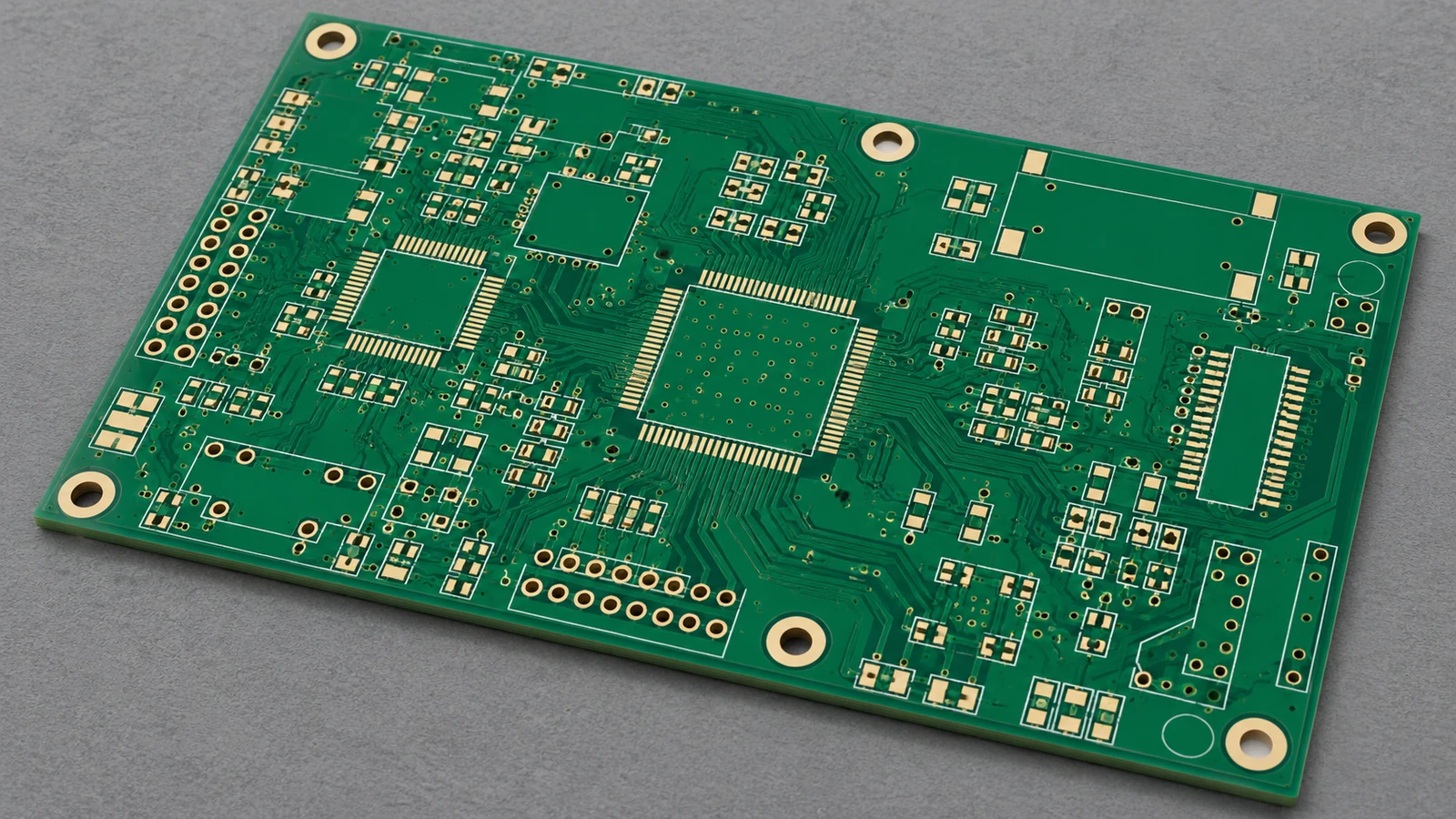
PCB stands for printed circuit board. Its copper traces, pads and other specified conductive features connect locations in the circuit. The insulating material supports and separates those conductors. Solder mask, surface finish, drilled holes and markings belong to the board fabrication specification where required; they do not turn an unpopulated board into a conventional PCBA.
A PCBA can carry resistors, capacitors, integrated circuits, switches, connectors and other fitted items. Solder commonly connects component terminations to the board. Some designs also use press-fit or other specified connections, so PCBA should not be interpreted as requiring solder at every connection.
| Item | Bare PCB | Assembled PCBA | Buyer Specification |
|---|---|---|---|
| Conductive board structure | Fabricated substrate, copper features and specified holes, mask and finish | The same board structure forms the assembly’s foundation | Board part number, revision and released fabrication requirements |
| Mounted components | No conventional mounted-component population | Components fitted according to the selected assembly variant | BOM revision, approved part numbers, quantities and do-not-populate positions |
| Soldered connections | Pads and finishes prepared for assembly; no component solder joints | Solder joints connect specified component terminations; other connection types follow the drawing | Assembly drawing, workmanship criteria and any special connection requirements |
| Firmware loading | No mounted programmable device to load | May be unprogrammed, programmed by the supplier, or programmed later by the OEM | Programming responsibility, image revision, configuration and verification method |
| Electrical verification | Can include bare-board continuity and isolation checks | Can include structural electrical tests and application functional tests | Named methods, product-specific limits, unit selection and required records |
Testing does not add components. A tested bare PCB remains a bare PCB, while an assembled board remains a PCBA even if the OEM performs its functional verification later. Compare quotation boundaries carefully: fitted hardware, programming, fixtures and acceptance testing can represent different amounts of work.
Use bare PCB and assembled PCBA in purchasing documents. Informal use of “PCB” for a populated board is common, but a purchase order needs a clear receiving condition.
A Labeled View of the Board, Components and Solder Joints
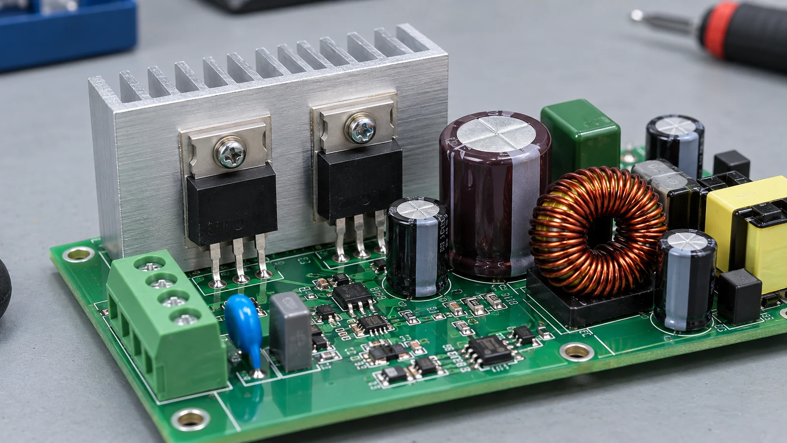
A conventional PCBA contains the board, the mounted parts and the connections between them. The board’s copper-layer count describes its internal construction; the assembly-side description identifies where components are fitted. Neither establishes the board’s programming or test status.
The simplified view below compares a bare board with an assembled section. Labels identify physical items, not a mandatory manufacturing sequence.
BARE PCB                               ASSEMBLED PCBA

No mounted components                  [R1 resistor]       [U1 integrated circuit]
                                        |         |         |               |
Exposed copper pads                     solder joints       solder joints
   [PAD]       [PAD]                     v         v         v               v
==== copper traces and pads ====       ==== copper traces and pads =============
---- insulating board material --      ---- insulating board material ----------
     plated holes, if specified              plated holes, if specified

Board fabrication deliverable          Board + fitted components + connections
                                       J1 connector, if fitted, links the board
                                       to its specified external interface

Separate delivery attributes: firmware version, test procedure and result record
R1 labels the resistor. U1 labels the integrated circuit. J1 labels the connector. These example reference designators connect physical items to the BOM and drawing; the diagram does not prescribe a particular stack-up, package or connector technology.
Mounting Method and Population Side
The conventional mounting groupings are SMT, through-hole and mixed technology. Surface-mount technology attaches component terminations to surface pads. Through-hole assembly places leads or pins through board holes. Mixed technology combines the two on one assembly. These descriptions help identify scope; the actual component packages and design determine the production route.
The complete population-side choices for this comparison are top-only, bottom-only and both sides. Count layers and populated faces separately. A board with copper on both faces can carry components on only one face, whose top or bottom designation must agree with the released drawing’s orientation.
Eurocircuits’ placement-data guide identifies component position, rotation, designator and mounting side as placement information. The buyer should keep those fields consistent with the assembly drawing and BOM, especially where a connector’s mating direction affects enclosure fit.
A partially populated variant can be a complete ordered assembly. If the released BOM intentionally leaves R12 and C8 unmounted, those empty positions are part of the approved configuration, not automatically missing-component defects.
Where Assembly Ends and Functional Verification Begins
Assembly creates the populated board; functional verification checks specified behavior under defined conditions. Inspection, programming verification and functional testing answer different questions. Specify each deliverable. The PCBA order must name the required activities and the evidence that permits shipment.
A visually acceptable solder joint does not establish that a sensor reports the correct value or that a controller communicates with its host. Eurocircuits’ published final-inspection description explicitly separates its inspection service from functional testing. The practical lesson is to define the test scope instead of relying on the word “assembled.”
| Verification Method | Question It Helps Answer | Main Boundary | RFQ Requirement |
|---|---|---|---|
| Visual inspection / automated optical inspection (AOI) | Are visible parts and joints consistent with the inspection criteria? | Optical access and the inspection program limit what can be assessed | Identify inspected features, applicable criteria and disposition of findings |
| X-ray inspection | Do selected hidden connections show relevant structural defects? | An image does not demonstrate application behavior | Identify packages, inspection extent and acceptance criteria |
| In-circuit test (ICT) | Do accessible circuits and components meet the selected electrical checks? | Access, circuit topology and test programming constrain fault detection | Agree the tested nodes, checks, limits and result format |
| Boundary scan | Do supported digital interconnections respond to the selected scan tests? | Requires suitable devices, accessible scan infrastructure and a test program | Specify applicable chains and interconnect tests |
| Functional test | Does the powered assembly perform the defined operations? | Results apply to the exercised functions and conditions | Release the procedure, stimulus, loads, limits and required records |
These methods can complement each other. Keysight’s manufacturing test overview distinguishes ICT, boundary scan and functional test, which is why a single “tested” checkbox leaves too much room for interpretation.
Programming Is a Separate Acceptance Item
Specify one programming arrangement: no programming required, OEM programming after delivery, or supplier programming before delivery. An analog board may need no firmware. A controller may require an application image, configuration data and device-specific settings.
Programming needs its own release identity. Specify the image revision, device configuration, supported verification method and record of the installed version so the supplier can demonstrate which content was accepted on each board. Texas Instruments’ C2000 flash guide describes programming and verification as explicit operations. Verifying written memory does not establish that the complete board passes its application tests.
State the Denominator Behind “100% Tested”
For integration-ready shipments, set the reference target at 100% of shipped units completing the agreed functional test, with an individual result linked to each serial number. This is a procurement benchmark, not a definition of PCBA or a claim of 100% fault coverage.
The test limits still matter. Checking supply rails and host communication does not also prove that every sensor input, load output and environmental condition meets the product specification, even when every board receives those two checks. Name the required functions and conditions.
Which Files Define a PCBA Purchase
A bare-board order defines the fabricated circuit board. A PCBA order must also identify which parts are fitted, how they are placed and connected, and which inspection, programming and functional verification activities the supplier must complete before shipment.
A filename is not a specification. Some manufacturing formats carry several data types, while other releases separate them into individual files; either approach needs a manifest identifying the controlling information and its revision.
| Released Information | Bare-Board Purchase | PCBA Purchase | Boundary to Resolve |
|---|---|---|---|
| Fabrication data and drawing | Defines the board to be manufactured | Defines the bare board used in assembly | Which board revision and fabrication requirements apply? |
| Bill of materials (BOM) | Normally unnecessary for conventional unpopulated boards | Defines fitted parts and the selected population variant | Who approves substitutes and intentional omissions? |
| Placement data / CPL | Not a component-assembly instruction for a bare-board-only order | Defines component locations, rotation and side where required | Which coordinate units, origin and orientation convention apply? |
| Assembly drawing and notes | May contain handling information relevant to fabrication | Defines polarity, special fitting, hardware and connection details | Which document controls mechanical or population discrepancies? |
| Firmware release and programming instruction | Outside the conventional bare-board scope | Required when supplier programming is included | Which image, configuration and verification record are required? |
| Acceptance and delivery specification | Defines board acceptance and shipment condition | Defines workmanship, tests, records, identification and packaging | What constitutes an acceptable shipped assembly? |
The schematic supports circuit and test review. It cannot replace a controlled Bill of Materials (BOM), placement definition or acceptance procedure, just as a photograph cannot reliably establish component substitutions, firmware identity or hidden connections.
Release one consistent package. Give every document an identifier and revision, name the selected assembly variant, and define a discrepancy rule that stops the affected build until conflicting revisions or part definitions are resolved.
An OEM can source the bare PCB separately and send it to an assembly supplier. The order must then identify who checks incoming boards, who owns shortages or rejected material, and which records accompany the transfer. Supplying the board does not remove the need to define assembly acceptance.
Standards and Acceptance Classes for a PCBA Order
A PCBA specification should identify the applicable assembly standards, agreed revisions and product class, while keeping bare-board requirements separate. A standards reference addresses its defined subject; it does not replace a product-specific functional test procedure.
IPC-A-600 addresses printed-board acceptability, while IPC-6012 addresses qualification and performance requirements for rigid printed boards. For the populated assembly, IPC J-STD-001J addresses soldering materials, processes and acceptance requirements; IPC-A-610J addresses post-assembly acceptability. The publisher’s 2024 revision announcement explains how the two assembly documents work together.
The official IPC J-STD-001J scope and classification excerpt identifies three end-product classes:
- Class 1: general electronics whose principal requirement is the completed assembly’s function.
- Class 2: electronics requiring continued operation and extended service life, where uninterrupted service is desirable but not critical.
- Class 3: electronics for which sustained or on-demand performance is critical, including demanding operating environments.
For an application where downtime is unacceptable, use Class 3 as the higher-demand acceptance starting point and review any application-specific requirements. Select the class from the actual end use. An ordinary controller does not automatically become Class 3 because it is sold to an industrial customer.
Record the standard identifier, edition and class before quoting. A generic claim of IPC compliance does not establish whether the purchase invokes IPC-A-600 for bare boards, IPC-A-610J for assembly acceptance, or IPC J-STD-001J for soldering requirements. Match the requirements to the design. A Class 3 designation does not automatically add firmware loading, coating, environmental testing or complete system validation to the order.
How Prototype and Repeat Orders Describe Deliverables
Prototype orders should describe what the engineering team needs to learn from the boards; repeat orders should preserve an approved configuration and shipment acceptance condition. Both need controlled revisions. “Build the same as last time” is insufficient when components, firmware or tests have changed.
For a prototype, identify the population variant and any deliberately deferred work. An OEM may order assembled boards for internal firmware development, with the supplier performing workmanship inspection and agreed electrical checks. Receiving then verifies that specific scope. It should not assume those development units are ready for installation in customer products.
Preserve the required debug access. State whether temporary connectors or test leads belong in the delivered assembly, and record authorized deviations so that a laboratory modification cannot silently become the next production configuration.
Repeat orders need a controlled baseline. Freeze the board, BOM, assembly drawing, firmware and acceptance-procedure revisions in the release manifest, then define how substitutions and changes are approved and linked to each shipped board’s identity and test record.
A previous prototype pass does not release every future board. If the recurring purchase calls for the integration-ready benchmark, every shipped unit must pass the agreed functional procedure. The procedure also needs review when a revision changes the behavior being checked.
Five Buying Situations That Need Different PCBA Scopes
The right PCBA deliverable follows the OEM’s next operation. A development team, an enclosure assembler and a service department can buy the same board design while needing different programming, test and record obligations.
| Buying Situation | Appropriate Deliverable | Scope to State Explicitly | Receiving Evidence |
|---|---|---|---|
| Firmware-development prototype | Assembled controller with agreed debug access | OEM loads development software after delivery; supplier performs the named assembly checks | Board/BOM revision, inspection result and approved deviation list |
| Repeat industrial HMI production | Programmed assembly accepted for the defined interface functions | Supplier loads the released firmware and tests every shipped unit under the agreed procedure | Serial-linked firmware and functional-test records |
| Sensor electronics sent to an OEM calibration station | Assembled board with specified preliminary checks | OEM performs final calibration; define any supplier programming and pre-calibration screening | Build identity, preliminary results and explicit calibration status |
| Control board installed behind a keypad and display | Assembly with the specified connectors and mounting hardware | Identify who supplies the mating parts and performs integrated interface checks | Assembly revision, connector orientation and required interface-test results |
| Replacement board for installed equipment | Service-compatible populated and configured board | Define approved hardware/firmware compatibility and the required service configuration | Part identity, programmed version and agreed release-test result |
These are purchasing scenarios, not claims about particular customer projects. Their differences affect where the board can go after receiving inspection.
A sensor PCBA awaiting calibration may be exactly the correct delivery for an OEM with its own calibration station. Calling it “fully tested” would still be ambiguous if the shipment record does not distinguish preliminary screening from the OEM’s final accuracy adjustment and verification.
An HMI controller has a different interface boundary. The board may communicate correctly on a fixture while a separately supplied keypad cable or display configuration still needs validation in the finished assembly. Name that integration owner before comparing quotations.
A replacement board adds compatibility as a receiving requirement. Matching the outline and connector count does not establish that firmware, pin assignments or the service configuration match the installed product. Record the accepted revision relationship in the order.
A Scope Statement Buyers Can Put in an RFQ
A PCBA RFQ should identify the shipped assembly, material ownership, assembly configuration, programming, acceptance and records. Put those obligations in the requested deliverable so that each supplier quotes the same work and identifies exceptions before the order is released.
The following completed example describes a noncritical industrial HMI controller. Its part numbers, revisions and quantity are illustrative buyer data, not an actual JASPER project or test record.
Supply 100 accepted units of HMI-104 PCBA, assembly revision C, standard population variant. The supplier provides the bare boards and all fitted components listed in the released BOM; substitutions require OEM approval before use.
Build to release manifest HMI-104-RC, comprising fabrication package FAB-HMI104-C, BOM-HMI104-C, placement file CPL-HMI104-C and assembly drawing ASSY-HMI104-C. Populate the top side only, using mixed technology: SMT parts and the specified through-hole connector J1. Leave R12 and C8 unpopulated as identified in the BOM and drawing.
Apply IPC J-STD-001J and IPC-A-610J, Class 2, with the approved assembly drawing’s requirements. Perform visual/AOI inspection under inspection plan IP-HMI104-C. Bare-board acceptance follows the released fabrication package.
Load firmware HMI-104 version 1.4.2 and configuration CFG-HMI104-02 using programming instruction PRG-HMI104-B. Verify the programmed content using the instruction’s approved method and record the installed version against each board serial number.
Functionally test 100% of shipped units to ATP-HMI104-B, using its specified supply, loads and limits. Include supply-rail checks, keypad-input response, indicator operation and host communication. Quote the required fixture and test setup separately. Record each unit’s serial number, procedure revision, measured values where required by the procedure, applied limits and pass/fail result. Release only passing units; repaired units must complete the required acceptance tests again.
Deliver depanelized boards in protective ESD packaging with assembly identification, serial list, inspection summary, programming record and individual functional-test results. Enclosure assembly, display installation, final system calibration and finished-product validation remain OEM responsibilities.
For a real order, the buyer supplies the actual identifiers, quantity and approved requirements in these fields. The named procedures must exist. They must contain executable checks and acceptance limits, so a supplier can price the work, run the agreed acceptance sequence and return the specified evidence.
Frequently Asked Questions About PCBA
PCBA purchasing questions are resolved by separating the physical board from the services and evidence attached to its delivery. The answers below apply to conventional populated circuit-board assemblies.
Does PCBA always include functional testing?
No. Functional testing is a purchase requirement. PCBA identifies the assembled board; the order must separately define the test procedure, operating conditions, acceptance limits and records. For integration-ready delivery, test every shipped unit against that procedure without confusing unit testing with detection of every possible fault.
Can an OEM buy the PCB and assembly separately?
Yes. Separate sourcing is possible. An OEM can supply purchased bare boards to an assembly provider, provided the parties define incoming acceptance, material responsibility, revision control and the required assembly records. The delivery remains a PCBA when it includes the specified fitted components and connections.
Is firmware programming part of PCBA by default?
No. Specify programming in the order. Identify who releases the image, who programs the device, and how the installed content or version will be verified and recorded. Successful programming verification confirms that operation; the agreed functional test checks the board’s specified behavior.
Which documents distinguish a bare-board order from a PCBA order?
A PCBA order adds controlled component, placement and assembly information to the board fabrication definition. The package normally includes a BOM, placement data where required, assembly drawings and acceptance requirements. Firmware instructions and functional-test procedures belong in the release when those services are ordered.
Does a completed PCBA mean a finished product?
No. Completion follows the purchase scope. A completed PCBA may still need an enclosure, display, wiring, calibration and system validation before the OEM can release the finished product. Identify the next integration owner and the requirements that remain after board-level acceptance.
Must a PCBA have a multilayer board?
No. Layer count describes board construction. PCBA describes the assembled state, whether the circuit design uses a simple board or a multilayer structure. Specify the required fabrication revision and assembly configuration; a minimum copper-layer count is not part of the PCBA definition.
Can components be mounted on both sides of a PCBA?
Yes. The population choices are top-only, bottom-only and both sides. The released drawing and placement data identify the correct face and orientation for each component. This population description is separate from the board’s copper-layer count and from its test status.
Is a partially populated board a completed PCBA?
Yes, if its fitted and intentionally omitted components match the ordered assembly variant. A do-not-populate position is different from an accidentally missing part. The BOM and assembly drawing should agree on those positions so receiving inspection can judge the correct configuration.
Prepare the Handoff Before Requesting a Quote
Prepare one released package that states what the OEM expects to receive: the bare-board revision, fitted population, assembly sides, programming status, acceptance procedure and shipment records. Assign the remaining integration work to a named party.
For a JASPER enquiry, use the PCB assembly services page with that package and the intended keypad, display or enclosure interfaces. Ask for a quotation against the defined assembly and acceptance scope. A precise handoff makes the PCB-versus-PCBA distinction useful at the point where it matters: comparing quotations and accepting the delivered boards.
Ready to Start Your Project?
Tell us about your membrane switch, keypad, or graphic overlay requirements. Our engineering team will review your specifications and provide a detailed quote.