Capacitive touch panel lifespan cannot be determined from an activation count alone. Eliminating a moving switching contact removes that contact’s wear mechanism; it does not establish the service life of the complete interface. A useful requirement defines how long a specified assembly must remain readable, bonded, and functionally reliable under its intended use and maintenance conditions.
Treat target service life as the required duration of acceptable operation. A reliability claim should identify the functions, conditions, exposure, and uncertainty attached to it.
For OEM procurement, ask a more precise question: What evidence shows that this configuration will keep accepting intended inputs—and rejecting unintended ones—through our service conditions?
- Separate Touch Detection from Mechanical Contact Wear
- Identify Cover, Bond, and Electronic Failure Modes
- Define Environment and Cleaning Exposure
- Compare Reliability Evidence at the Same Boundary
- Turn the requirement into an auditable test record
- Plan Maintenance and Change Control
- Specify the Reliability Evidence You Need
Separate Touch Detection from Mechanical Contact Wear
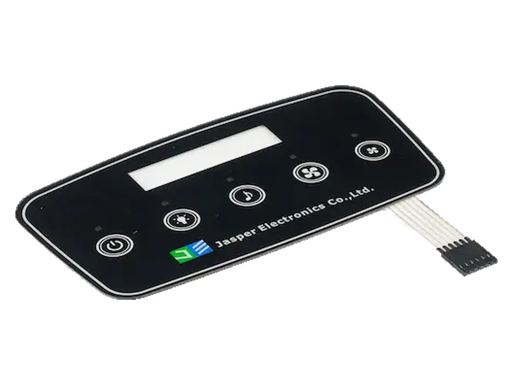
A capacitive key detects an electrical change rather than repeatedly closing a mechanical switching contact. However, the assembly may still contain connector contacts, bonded layers, and separate electronics. The referenced supplier’s capacitive touch technology guide illustrates these construction and interconnection distinctions; it does not establish a lifespan for another manufacturer’s assembly.
A capacitive touch cycle life claim needs a defined counting point. Treat a physical touch-and-release cycle, a controller detection, and a host-accepted command as separate events. A firmware counter can demonstrate activity at its logging point without proving that the cover remained intact, releases were recognized, or the intended host command occurred.
For fixed-function keys, specify press, hold, release, missed-input, duplicate-input, and unintended-input behavior. A PCAP coordinate screen needs a separate plan for position accuracy, edges, and simultaneous contacts where supported. Do not transfer a coordinate-screen endurance claim to a fixed keypad merely because both use capacitive sensing.
When specifying custom capacitive touch panels, identify whether the purchase covers the front layer and sensor only or also the controller and tuned firmware. Assign responsibility separately for the cover, sensor, controller hardware, firmware, display, and host application. The capacitive touch panel design guide provides broader configuration and integration context; the reliability record should identify the exact configuration being qualified.
Identify Cover, Bond, and Electronic Failure Modes
Evaluate each layer and the complete input path, not just whether the sensing circuit still responds. Use the following illustrative review template to identify candidate failure mechanisms and the evidence needed to investigate them. These are planning prompts, not measured results or diagnoses.
| Component or function | Potential failure mechanism | Observable symptom to investigate | Verification evidence to request |
|---|---|---|---|
| Cover or lens | Abrasion, impact damage, chemical attack | Scratches, cracking, haze, unsafe edges | Actual-grade specimens with production finishing; documented exposure and before/after inspection |
| Printed legends and coating | Surface wear or exposure-related deterioration | Faded markings, lost contrast, coating damage | Production print/coating construction; agreed legibility and appearance checks after exposure |
| Adhesive and bonded interfaces | Separation, edge lifting, moisture-related bond deterioration | Bubbles, lifted edges, changed touch response | Bond inspection and appropriate adhesion checks, paired with functional tests on aged assemblies |
| Sensor conductors and tail | Strain damage, conductor cracking, corrosion | Dead or intermittent channels | Continuity checks and installation/service loading on the specified routing and bend history |
| Connector and termination | Contact degradation, latch damage, poor retention | Intermittent electrical connection | Exact mating parts, retention checks, and applicable mating-cycle evidence |
| Controller and electronics | Electrical damage, supply instability, component degradation | Resets, lost channels, unstable operation | Powered testing with supply, reset, communication, and functional logs |
| Firmware and host integration | Configuration defects, state or recovery errors—not physical software wear | Duplicated commands, missed releases, stalled input | Versioned configuration and synchronized controller/host event records |
| Display or feedback, when included | Failure in the separate indication path | Correct input with missing or misleading confirmation | Separate indication checks correlated with accepted host commands |
Two boundaries deserve particular attention. The overlay, inks, adhesives and unintended air gaps can affect sensing performance. Inspect an aged bond together with touch behavior; visual bond condition alone does not answer whether the assembled sensor still operates correctly.
Distinguish environmental drift from permanent damage. For the MTCH1060 example, uncompensated sensor drift can affect detection and sensitivity; do not assume every controller uses the same compensation. Record behavior during exposure and after recovery before calling an intermittent symptom irreversible aging. For tails, distinguish installation bending from repeated service flexing: “flexible” is not a dynamic-flex rating, so require evidence for the intended movement.
For the visible interface layer, specify graphic overlays by their actual substrate, print, finish, and assembly conditions. A material name alone is not the finished panel’s reliability specification.

Define Environment and Cleaning Exposure
Describe service life through separate workload, time, and exposure requirements. A touch counter should be one part of that description, not the substitute for it.
For a constant-use planning estimate:
Planned touches per key = touches per operating day × operating days per year × target years
Planned cleaning events = cleaning events per operating day × operating days per year × target years
These are workload calculations, not lifespan predictions. Use separate periods when duty changes. Track the busiest key rather than averaging activity across the panel, and define touch duration, release interval, and any intended hold or repeat behavior.
Record powered hours, calendar age, storage, and unpowered exposure separately. Define the relevant temperature and humidity conditions, condensation, light exposure, contamination, vibration, installation strain, and service handling. Select conditions from the intended application rather than borrowing the most impressive limits from an unrelated datasheet.
For cleaning, record the formulation, dilution, contact time, surface temperature, cloth, wiping force or controlled method, frequency and drying or rinsing procedure. Evaluate cleaner selection and scratch avoidance together. Guidance for an acrylic material alone does not approve the complete printed and bonded touch assembly.
Request current documentation for the actual material grades, then assess production-representative assemblies. Where service combines cleaning and environmental exposure, define their sequence and intermediate checks instead of assuming separate coupon passes prove combined-use durability.
Increasing the tapping rate does not reproduce every calendar-aging mechanism. NIST’s physical-acceleration guidance describes acceleration in terms of the same failure mechanism occurring on a changed timescale. Without that connection, a fast test supplies a test result—not a justified prediction of years in service.
Compare Reliability Evidence at the Same Boundary
Compare numbers only after matching what was tested, how it was stressed, and what counted as failure. Here, the boundary means the included components, configuration, operating conditions, and measured output.
Use this comparison sheet against both suppliers’ reports. Record differences before ranking their headline figures.
| Comparison item | Information to align in both reports | Why unmatched results are not equivalent |
|---|---|---|
| Test object | Material coupon, bare sensor, bonded panel, or installed system | A passing layer does not establish complete-system performance |
| Configuration | Material grades, stack, controller, firmware, host, and mounting revisions | Different revisions may not represent the ordered assembly |
| Counted event | Applied stimulus, detected touch, completed release, or accepted command | Counters at different stages measure different outcomes |
| Workload | Per-key cycles, dwell, release interval, fixture, and contact conditions | Different stimulation patterns do not represent the same duty |
| Time and exposure | Powered hours, storage, cleaning, environment, and test sequence | Rapid cycling alone does not include untested exposure |
| Population | Specimen count, production lots, and exposure per specimen | Adding cycles across units is not the cycle endurance of each unit |
| Acceptance | Appearance, bond, input, release, unintended-event, and recovery limits | “Still responds” is narrower than full interface acceptance |
| Result type | Design target, qualification result, run-to-failure result, or field dataset | A target or planned test endpoint is not a demonstrated failure limit |
| Statistical claim | Model, confidence, failures, test duration, and excluded observations | Similar headlines may express different uncertainty |
Ask for the observations behind “passed,” including failures, interventions, retuning, resets, and specimens removed from testing. Preserve exposure completed by units that had not failed when the test ended. NIST’s reliability-test guidance shows that statistical conclusions depend on the test plan and model; its exponential/HPP methods require their stated assumptions, not automatic application to every panel.
Turn the requirement into an auditable test record
Define limits before testing. The following is an illustrative record template, not a prescribed qualification standard. Actual-result cells are intentionally blank.
| Test object | Exposure or repetition to specify | Acceptance rule to agree before testing | Actual result |
|---|---|---|---|
| Installed fixed-key assembly | Per-key workload, fixture, dwell, and release sequence | For a momentary, non-repeat key: one intended command per valid cycle; correct release; agreed timing and unintended-event limits | |
| Printed, bonded front assembly | Defined cleaning repetitions and exposure sequence | Approved appearance, legibility, and bond limits; required touch behavior after exposure | |
| Powered integrated assembly | Environmental schedule and operating modes | Defined input behavior during operation; documented recovery, reset, and fault criteria | |
| Service-reassembled unit | Approved replacement or connector-mating procedure and repetitions | Correct routing and retention; required appearance, bond/seal, and input checks |
Record specimen and lot identifiers, drawing and software revisions, fixture setup, exposure history, baseline readings, intermediate findings, and final results. Distinguish behavior during stress from behavior after recovery. A final room-temperature check cannot answer an unmeasured during-exposure requirement.
Plan Maintenance and Change Control
Make inspection, replacement, and change review part of the reliability agreement. Assign who checks the surface, bonds, tail, connector, and event behavior, and how findings trigger repair or removal from service.
Define acceptable cosmetic change separately from unreadable controls, cracked surfaces, exposed circuitry, or unreliable input. Set inspection intervals and replacement triggers from application risk and available evidence rather than inventing a universal maintenance schedule.
Maintain a controlled record of cover grade and thickness, coating, ink, adhesive, sensor layout, tail routing, connector, controller, firmware, host software, and mounting configuration. For each proposed change, document the affected functions and choose proportionate requalification. Do not assume that an unchanged outline means unchanged reliability.
After an authorized repair, verify both the restored assembly and its interaction with the host. Preserve field-return evidence before changing its condition. Keep any safety-related function under its separate safety requirements; ordinary-key endurance approval is not a safety-function approval.
Frequently Asked Questions
Use these questions to resolve evidence gaps before approving a supplier report or replacement procedure.
Can a controller MTBF figure predict the panel’s replacement date?
No. MTBF means mean time between failures; it is not a scheduled replacement date. A controller figure does not cover the lens, adhesive, interconnects, firmware integration, or host. Ask which items, operating conditions, and failure-rate assumptions the figure includes.
Should I reject a report that shows no failures?
No. A zero-failure report can be useful, but its strength depends on sample size, exposure, representativeness, and the statistical method. Request those details and the confidence statement rather than interpreting “no failures observed” as “no failures possible.”
Can accelerated testing be converted directly into years of service?
Only with a justified model connecting test stress to the relevant field failure mechanism. Request the model, supporting data, use conditions, and uncertainty. Without them, report the completed test exposure rather than an equivalent number of service years.
Can we keep the old approval after changing the cleaner?
Do not assume so. Compare formulation, concentration, dwell, wiping method, and frequency with the approved process. Review the actual cover, coating, print, and bond, then select compatibility and functional checks that address the change.
Can a damaged cover be replaced without replacing the sensor?
Only when the assembly design and repair procedure permit it. Define who controls removal, rebonding, thickness, contamination, and sealing where applicable. Verify appearance and touch-to-host behavior after repair; do not assume every laminated panel is field-serviceable.
Does an IP rating demonstrate reliable operation with water on the keys?
No. An IP classification concerns enclosure protection. Wet-surface recognition, unintended inputs, lockout behavior, and recovery need their own functional criteria. Confirm both the enclosure test configuration and the required touch behavior for the intended wet condition.
What should accompany an intermittent field-return sample?
Preserve the configuration and evidence before cleaning, resetting, or disassembly. Send the serial or lot identifier, firmware versions, installation photos, cleaner history, exposure history, and timestamped controller and host logs where available. State whether drying or restarting changed the symptom.
Specify the Reliability Evidence You Need
Send the service profile and acceptance requirements together with the drawing. Include the panel configuration and supply boundary, controller and firmware ownership, target service duration, per-key workload, powered hours, cleaning process, environment, maintenance plan, and prototype and production quantities.
Share My Reliability Requirements to start a configuration-specific RFQ discussion, with required evidence identified separately from any proposed lifespan claim.
Ready to Start Your Project?
Tell us about your membrane switch, keypad, or graphic overlay requirements. Our engineering team will review your specifications and provide a detailed quote.