
OEM force sensing resource
Force Sensing Resistor vs Strain Gauge: Choose the Load Path, Not the Sensor Name
Choose a force sensing resistor when the product needs a thin, local, force-related signal and the contact stack can be calibrated with the sensor. Choose a strain-gauge transducer when load can pass through a controlled elastic member and the project needs a calibrated structural force path. The correct decision starts with mechanics, not a sensor name.
Choose a force sensing resistor when the product needs a thin, local, force-related signal and the contact stack can be calibrated as part of the measurement. Choose a strain-gauge transducer when the product can route load through a controlled elastic member and needs a calibrated relationship between structural deformation and force. Neither technology measures force independently of mechanics. The FSR result is shaped by the contact patch, support, film stack, and loading history. The strain-gauge result is shaped by the spring element, gauge installation, bridge, temperature, mounting, and load introduction.
For an OEM seat or flexible sensing program, JASPER’s FSR seat pressure sensor page is the commercial route when a force-sensitive resistive construction may fit the required load path. The quotation must still confirm whether FSR is the correct sensing principle. JASPER does not supply or claim a strain-gauge load-cell product on that page, and this comparison does not turn an FSR into a precision load cell.
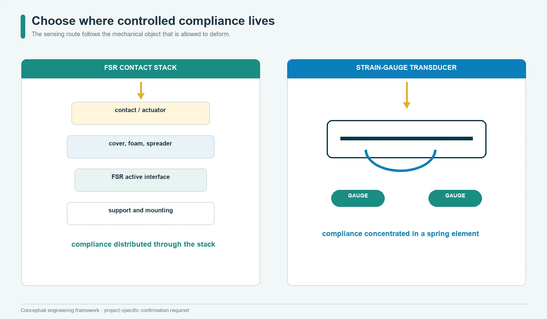
Choose the Location of Compliance Before Choosing the Sensor
Every force-measurement system must deform somewhere. That deformation may be concentrated in the sensing interface, spread through foam, or designed into a metal or polymer spring element. The location of compliance determines which variables become part of the calibration.
In an FSR route, the force-sensitive element and the immediate contact stack are intentionally involved in the response. A load spreader, actuator, foam, protective film, adhesive, backing, and housing can all change the force transferred into the active area.
In a strain-gauge route, the design usually creates a repeatable elastic body. Bonded gauges detect small strain in selected locations on that body. The contact point, mounting, side load, bending mode, gauge pattern, bridge wiring, and mechanical stops determine whether the intended load produces the expected strain.
The first design question is therefore:
Where is the approved elastic deformation, and who owns its geometry, material, mounting, and limits?
If that question has no answer, a sensor comparison table will not close the measurement risk.
Compare a Sensing Element With a Complete Transducer
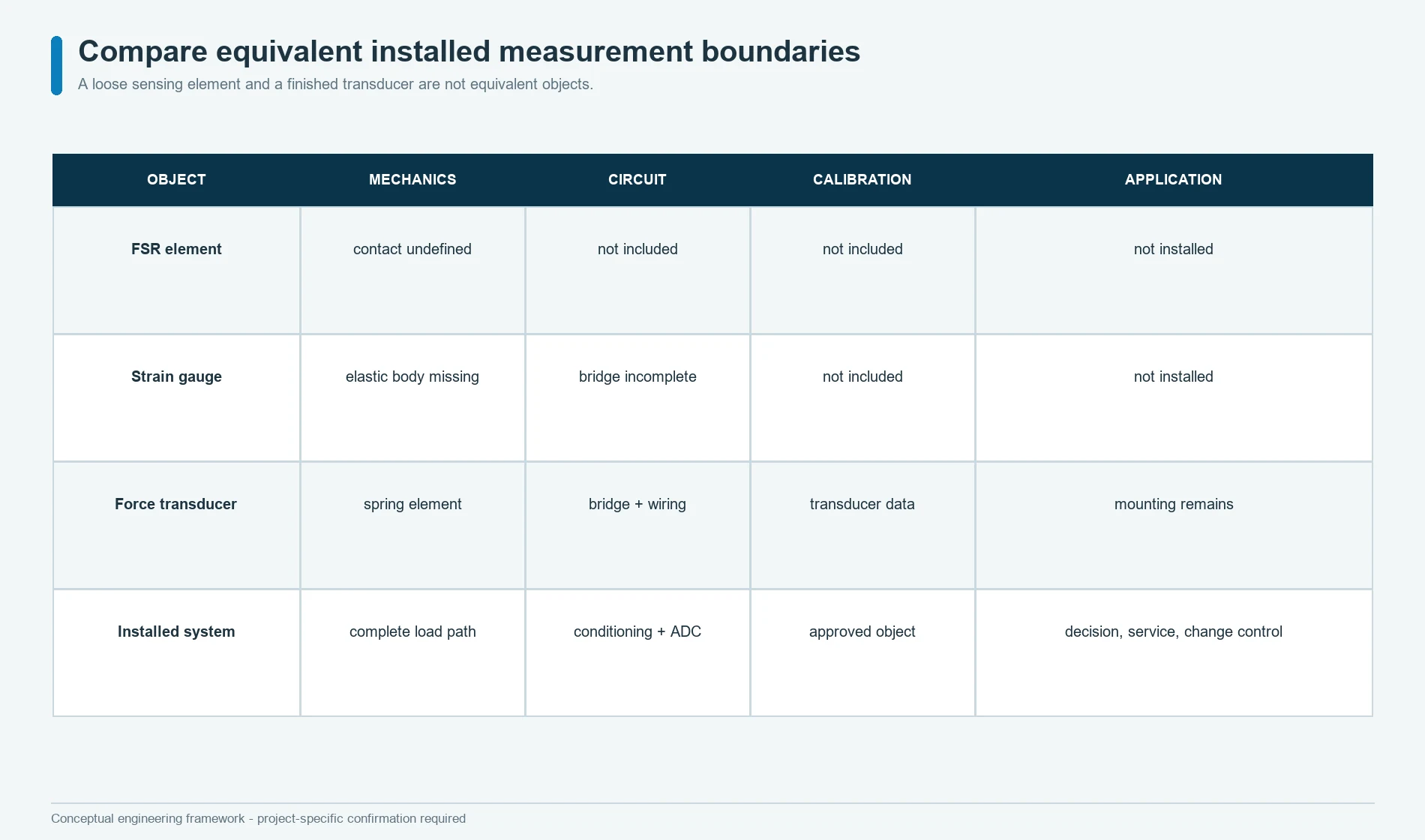
Force sensing resistor, strain gauge, force transducer, and load cell describe different levels of a system.
| Term | What it is | What is still missing |
|---|---|---|
| Force sensing resistor | a resistive sensing element whose resistance normally decreases as applied force increases | controlled contact, support, circuit, calibration, protection, and acceptance |
| Strain gauge | a resistive element bonded or otherwise attached to a part so resistance changes with strain | elastic member, gauge placement, bridge, wiring, temperature control, mounting, and calibration |
| Strain-gauge force transducer | an elastic measuring body instrumented with strain gauges and electrical connections | application mounting, signal conditioning, calibration use, overload control, and system validation |
| Load cell | a force transducer configured to measure load in a defined mechanical direction and range | correct load introduction, structure, cabling, instrumentation, installation, and traceability |
Interlink identifies the FSR 400 family as force-sensing resistors whose resistance changes with applied force.[1][2] HBK describes strain-gauge force transducers as spring elements carrying strain gauges that convert deformation into an electrical signal.[6] Those definitions are useful only if the buyer compares equivalent system boundaries.
Do not compare the price or thickness of a loose FSR with the price or height of a finished load cell and call the result a technology decision. Compare the complete installed measurement chains.
An FSR Measures Through a Contact Interface
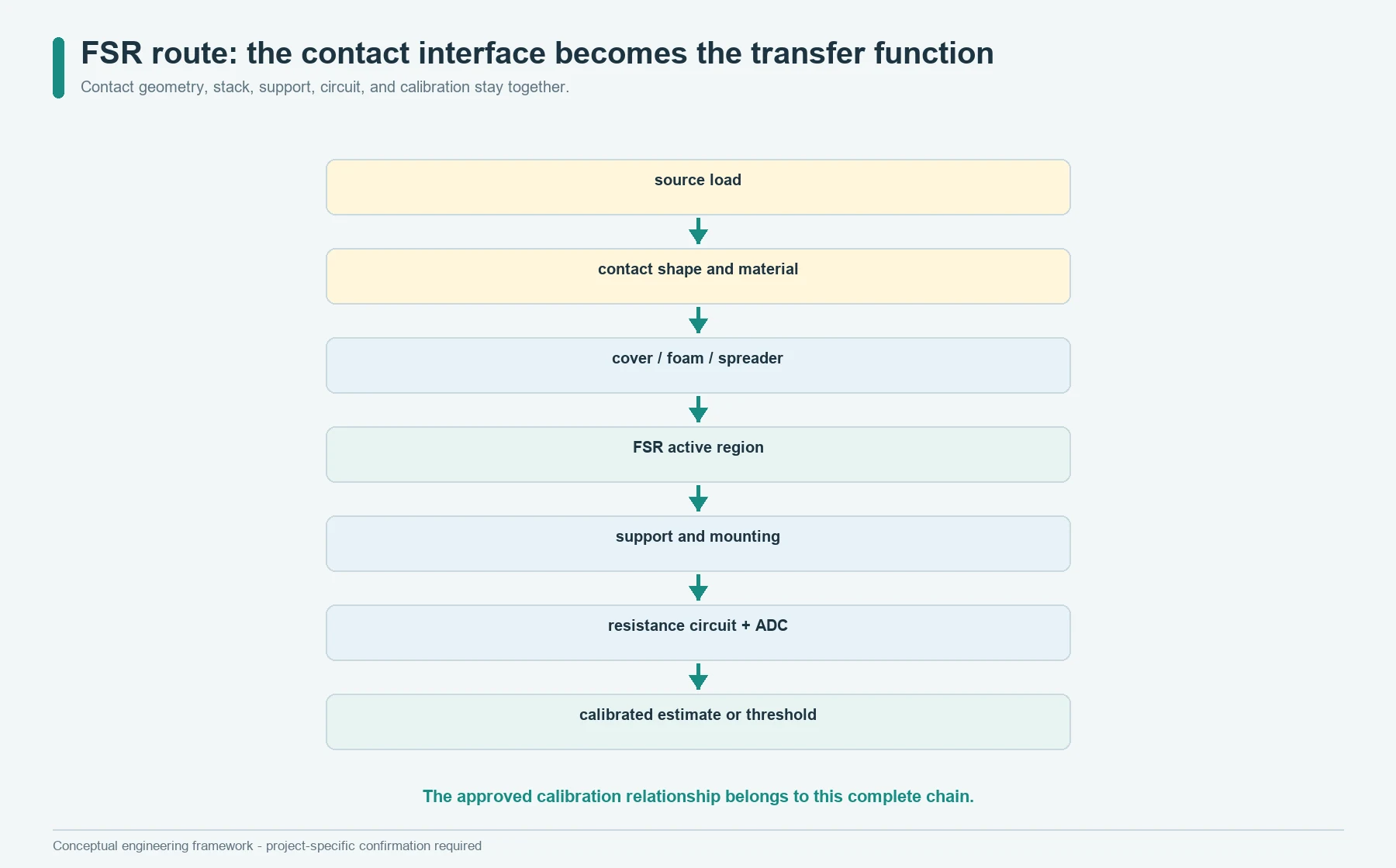
An FSR does not receive a pure abstract force. It receives a distribution of normal load over a physical area. The conductive and resistive structures respond to the way that load reaches the active region.
The measurement object is:
source load
    |
contact shape and material
    |
load spreader or concentrator
    |
cover, foam, film, adhesive, or protective layer
    |
FSR active area and support
    |
resistance or conductance
    |
measurement circuit
    |
calibrated estimate, band, or threshold
Interlink’s integration guide treats actuator geometry, force distribution, support, mechanical stops, and calibration as part of FSR use.[2] Tekscan likewise states that thin force sensors need controlled loading and calibration in the intended setup.[3][4]
This route can be valuable when the product has little depth, needs a flexible sensing zone, or uses a local force threshold. It is weak when the buyer expects the sensing film to ignore uncontrolled contact area, foam behavior, preload, shear, or housing motion.
The FSR is not merely installed in the product. The nearby mechanics become part of its transfer function.
A Strain Gauge Measures Deformation in an Elastic Member
A strain gauge changes resistance as the surface carrying it strains. Strain is the relative change in length:
strain = change in length / original length
The gauge factor relates fractional resistance change to strain:
gauge factor = (change in resistance / original resistance) / strain
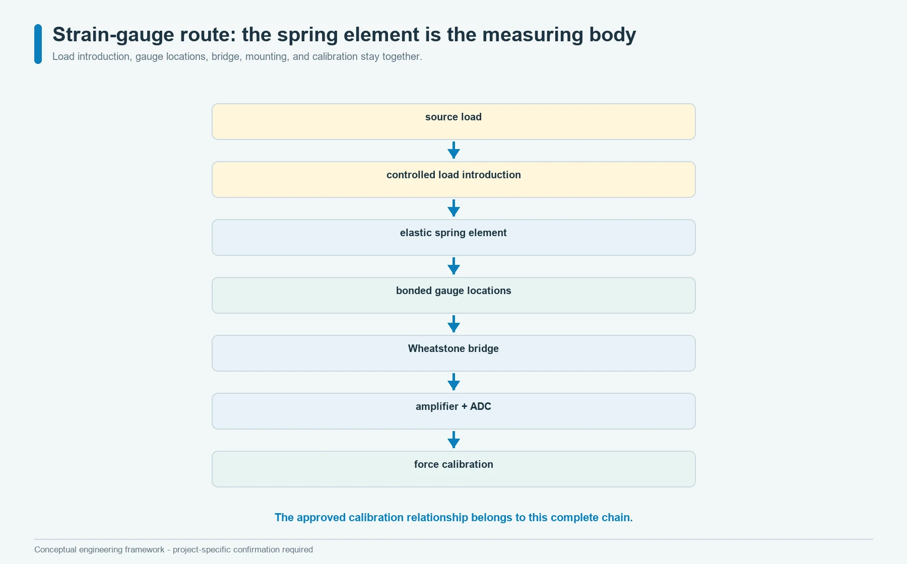
These relationships do not produce force by themselves. Force is inferred because the transducer designer knows how the approved elastic member deforms under the intended loading mode.
HBK’s force-transducer material describes the spring element as the body that converts force into strain at the gauge locations.[6] Its load-cell overview shows the broader path from applied load through deformation and bridge output.[7] Micro-Measurements’ strain-gage sensor guide emphasizes sensor pattern, backing, adhesive, installation, material, temperature, and application selection.[10]
The elastic member can improve measurement control because it defines where strain should occur. It also adds responsibility. Material condition, machining, heat treatment, geometry, residual stress, gauge bonding, moisture protection, cable forces, mounting, and overload history can all alter the result.
The Two Signal Chains Assign Responsibility Differently
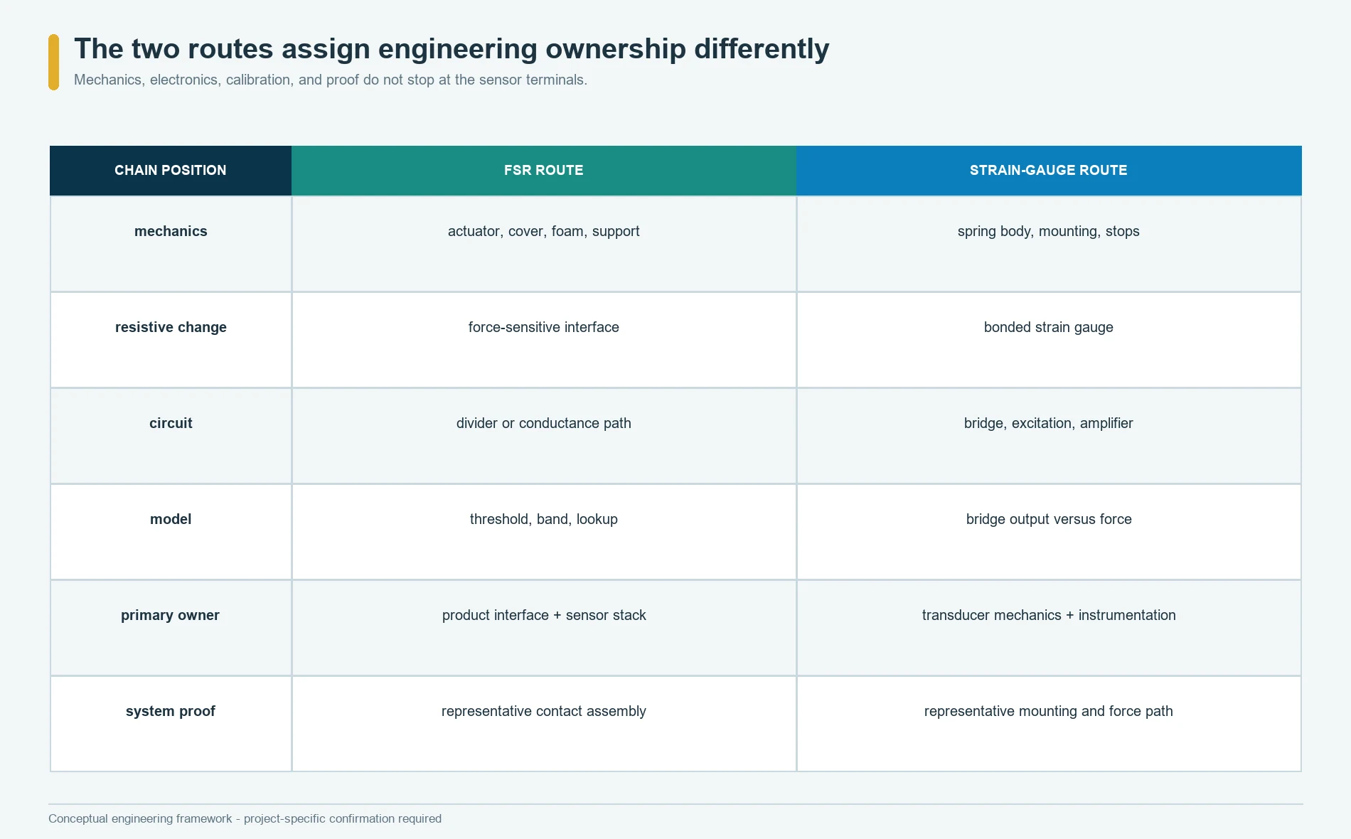
The architectures can be placed side by side:
| Chain position | FSR route | Strain-gauge route |
|---|---|---|
| source load | finger, occupant, clamp, object, actuator, or distributed contact | applied load entering a designed force path |
| mechanical converter | contact patch, spreader, foam, cover, support, and sensor stack | elastic member, flexure, beam, diaphragm, column, or other spring body |
| resistive change | force-sensitive material and internal contact behavior | strain gauge bonded to the strained surface |
| circuit | divider, conductance circuit, amplifier, comparator, or ADC | quarter, half, or full bridge plus excitation and instrumentation |
| mathematical model | threshold, relative band, lookup table, or fitted relation | bridge output versus force calibration, with compensation and corrections |
| dominant ownership | product-interface and sensor-stack team | transducer mechanical, gauge-installation, and instrumentation team |
| system proof | representative contact and assembly | representative mounting and applied-force path |
Neither column ends at the sensor terminals. The FSR team cannot ignore the contact mechanics. The strain-gauge team cannot ignore the spring element and mounting.
The seat occupancy sensor product hub is useful when a seat project still needs to choose among contact mats, FSRs, multi-zone flexible sensors, and other occupancy routes. A structural strain-gauge solution belongs to a different supplier and validation boundary unless JASPER engineering explicitly confirms otherwise.
Contact Geometry Is the FSR Transfer Function
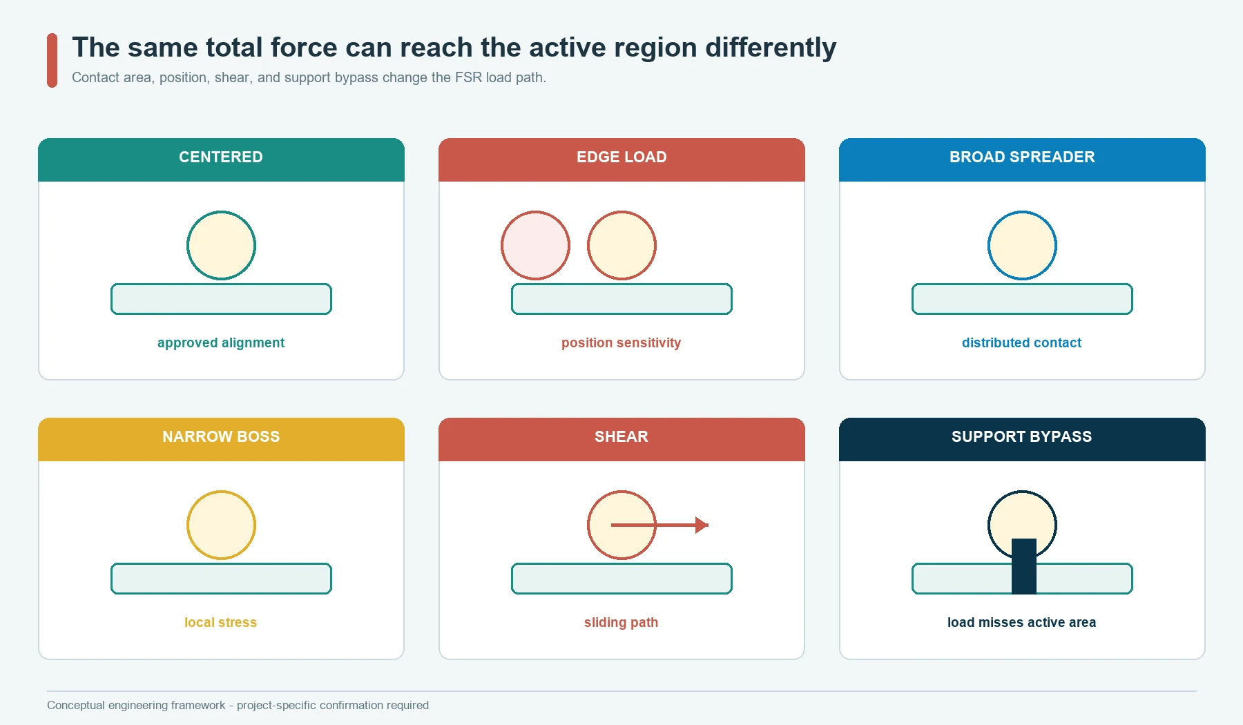
Two test fixtures can apply the same total force and produce different FSR outputs if they use different contact areas, hardness, alignment, curvature, or support.
Review:
- actuator size and edge shape;
- material hardness and surface finish;
- active-area coverage;
- centering and angular alignment;
- backing stiffness and flatness;
- protective and adhesive layers;
- preload and compression at zero target load;
- permitted shear or sliding;
- overtravel and mechanical stop;
- foam or elastomer dwell and recovery;
- production tolerance and wear.
The interface can act as a load concentrator, spreader, cushion, spring, or bypass. If a rigid boss touches only part of the active region, local stress and position matter. If foam covers a large area, load distribution and time-dependent compression matter. If a cover bridges onto the sensor border or nearby housing, some load may bypass the sensing region.
The final drawing should name the contact object and support condition. Apply force to sensor is not enough.
The Spring Element Is the Strain-Gauge Transfer Function
A strain gauge can be stable while the transducer is wrong because the spring element does not receive the intended loading mode.
The spring-element record should identify:
- material and condition;
- geometry and critical sections;
- nominal load direction;
- mounting and constraint surfaces;
- load-introduction point and hardware;
- bending, tension, compression, shear, or combined mode;
- gauge locations and orientations;
- strain field expected at each gauge;
- mechanical stops and overload path;
- cable and connector force isolation;
- environmental protection;
- inspection and traceability.
Side load, moment, eccentricity, mounting flatness, fastener behavior, and structural stiffness outside the transducer can redistribute strain. A calibrated transducer can therefore produce a biased result after installation if the product loads it differently from the calibration setup.
The spring element is not packaging around the strain gauges. It is the mechanical measuring component.
Resistance Change and Bridge Output Need Different Electronics
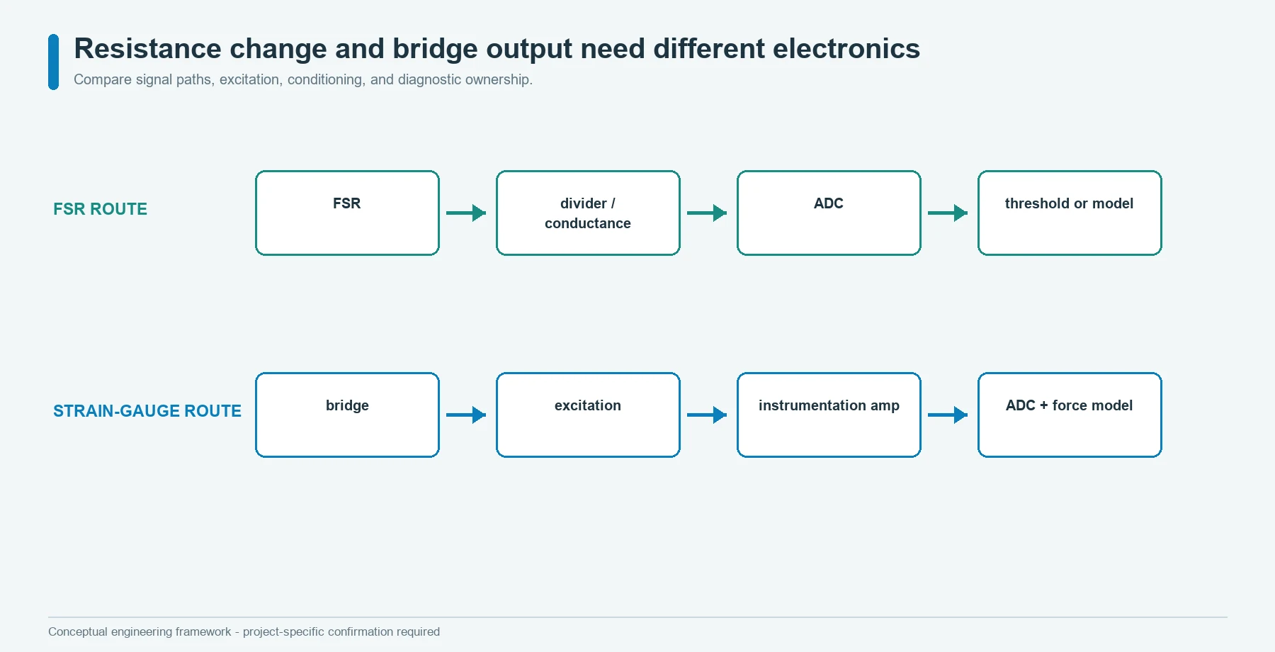
An FSR is commonly read as a changing resistance or conductance. The selected circuit shapes sensitivity, direction, usable span, current, noise, ADC utilization, and fault detection. The circuit must be chosen for the force-related region that matters, not for the full generic curve in a catalog.
A strain-gauge transducer commonly uses a Wheatstone bridge. HBK describes the bridge as a circuit that converts small resistance changes into a differential electrical output.[8] The bridge can also use gauge placement and wiring to increase the desired response and reduce selected common effects.
Compare the electronics as systems:
| Electrical question | FSR route | Strain-gauge route |
|---|---|---|
| excitation | supply and measurement circuit chosen for the resistance region | stable bridge excitation |
| raw signal | resistance, conductance, or conditioned voltage | small differential bridge output, often expressed relative to excitation |
| amplification | optional depending on threshold and ADC plan | instrumentation gain is normally part of the chain |
| offset | unloaded resistance may be very high or load-stack dependent | bridge zero includes gauge, bond, wiring, mechanical, and temperature effects |
| diagnostics | open, short, out-of-range, stuck, or implausible transition | bridge imbalance, open lead, short, excitation, overload shift, or drift |
| calibration storage | threshold, curve, lookup table, or assembly coefficients | zero, span, correction, and transducer identification |
More ADC bits do not repair unstable mechanics. A low-noise bridge amplifier does not correct eccentric loading. A sophisticated FSR curve does not correct changing contact geometry.
Calibrate the Object That Will Remain in Production
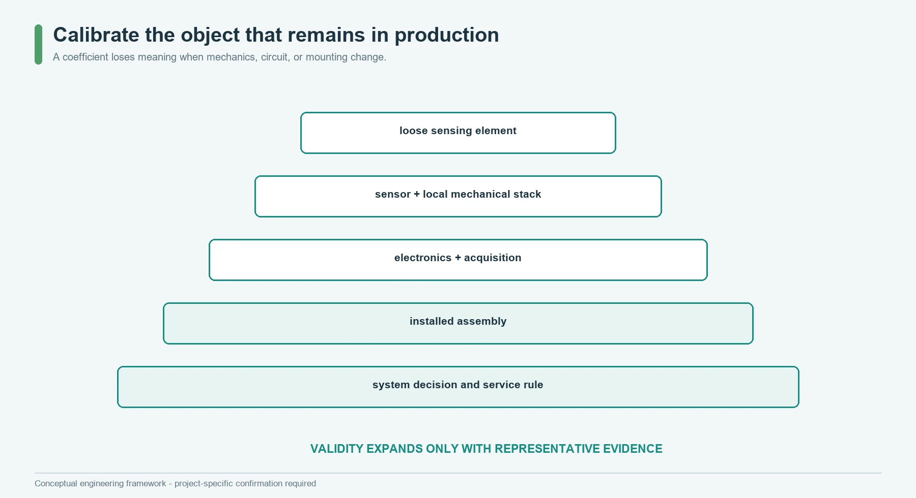
Calibration transfers a known input into a relationship between input and output. The calibrated object must match the object that production and service will use.
For an FSR system, decide whether calibration belongs to:
- the loose sensing element;
- sensor plus approved actuator and support;
- finished subassembly;
- complete seat or product stack;
- each unit, a sample family, or a common model.
A loose-sensor curve may help incoming comparison, but it cannot approve a seat cushion, foam stack, adhesive, enclosure, or customer actuator that changes load transfer.
For a strain-gauge route, decide whether calibration belongs to:
- the bonded spring element;
- assembled force transducer;
- transducer plus mounting hardware;
- complete machine or seat structure;
- each serial number or a controlled family.
NIST describes force-transducer calibration through comparison with known forces and notes that the calibration applies to the defined transducer and conditions.[11] ASTM E74 and ISO 376 provide practices for calibrating force-measuring instruments used in testing machines.[12][13] They do not make an unrelated product fit the application or remove installation effects.
The calibration certificate, model, coefficients, fixture, orientation, mounting, cable, instrument, and environmental conditions must refer to the same measurement object.
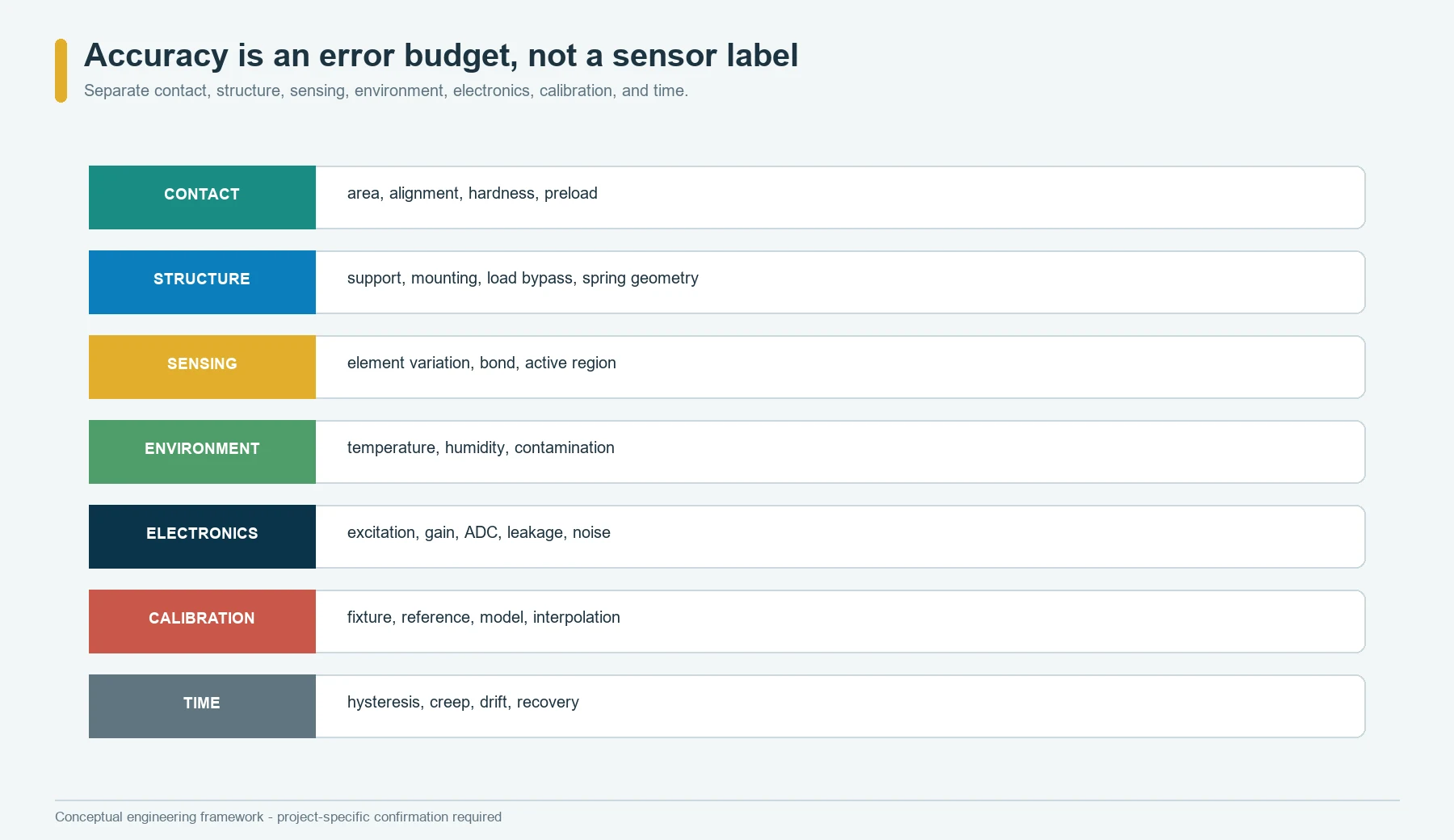
Accuracy Is an Error Budget, Not a Sensor Label
FSR accuracy and strain-gauge accuracy are incomplete phrases. The required result may be a threshold decision, relative force band, calibrated force, repeated process signature, or traceable test-machine indication. Each result has a different error budget.
Build the budget by source:
| Error source | FSR route | Strain-gauge route |
|---|---|---|
| load introduction | contact position, area, hardness, shear, support | eccentricity, side load, moment, mounting, alignment |
| mechanical response | film stack, foam, adhesive, cover, backing | spring material, geometry, residual stress, fasteners |
| sensing element | unit variation, nonlinearity, hysteresis, creep | gauge factor, transverse sensitivity, installation, bond |
| environment | temperature, humidity, material conditioning | temperature, thermal expansion, moisture, protection |
| electronics | resistor, supply, ADC, filtering, leakage | excitation, amplifier, bridge, lead resistance, noise |
| calibration | fixture mismatch, limited points, load history | force standard, mounting, orientation, interpolation, zero |
| time | dwell, recovery, wear, assembly settling | creep, zero return, fatigue, overload history |
Only after the required output and conditions are defined can the team decide which terms matter and how they combine.
Do not publish one percentage as if it includes every row. Do not call one route more accurate without naming the calibrated object, range, conditions, time, and uncertainty or acceptance model.
Linearity and Resolution Can Be Misleading
FSR response is commonly nonlinear. A fitted curve can make the displayed relationship look linear over a selected region, but the correction is valid only for the sensor and mechanics represented by the data.
A strain-gauge transducer can be designed for a more linear force-to-output relationship, but the result still depends on elastic-body geometry, loading mode, bridge configuration, mounting, temperature, and calibration. Gauge resistance changes are small; bridge and amplifier design determine whether the system resolves them without adding unacceptable noise or drift.
Separate:
- sensor nonlinearity;
- fitted-model residual;
- repeatability;
- resolution;
- threshold margin;
- calibration uncertainty;
- display rounding;
- out-of-range behavior.
Resolution is the smallest output change the electronics can distinguish under stated conditions. It is not automatically the smallest force change the mechanics can measure reliably.
For a binary occupancy or press decision, classification margin can be more valuable than a finely resolved force value. For a calibrated force transducer, resolution without stability and uncertainty is also incomplete.
Hysteresis and Creep Begin in Different Places
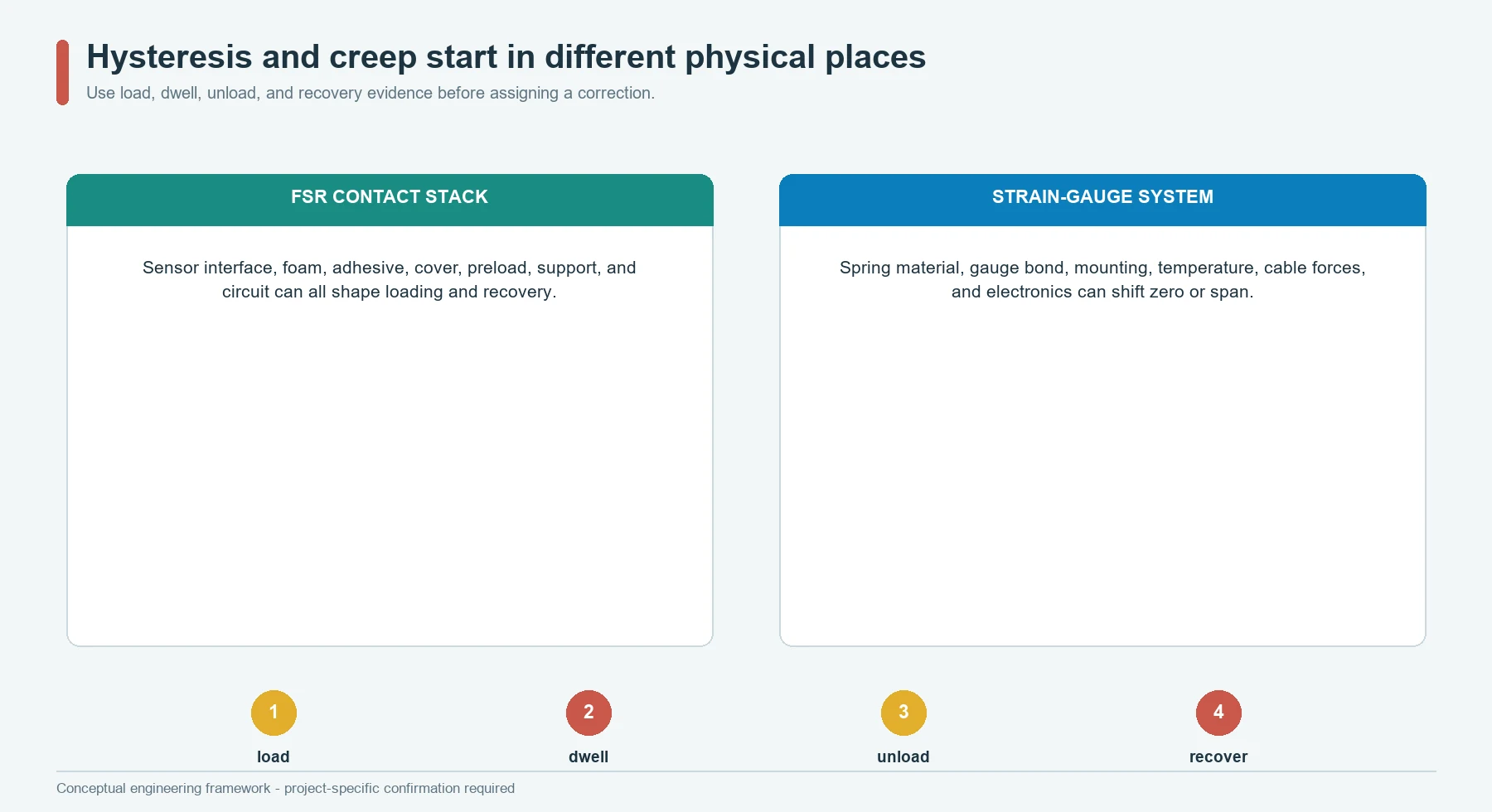
FSR hysteresis can include force-sensitive material behavior, internal contact changes, actuator friction, foam, adhesive, support deformation, and load history. Creep can appear as output change while a constant load remains applied. Recovery after unloading can depend on both the sensor and the surrounding viscoelastic stack.
Strain-gauge transducers can also show hysteresis, creep, and zero return. The sources may include the elastic member, adhesive, gauge backing, protective system, mounting friction, fasteners, cable forces, material history, and overload.
Use a common observation plan:
- approach each force from below and above;
- record loading and unloading;
- hold selected loads for the required dwell;
- record output during the hold;
- unload and record zero return;
- repeat after relevant conditioning;
- identify which component changed before editing the calibration.
Calling all time-dependent output sensor drift hides whether the cause sits in foam, a contact interface, a bonded gauge, an amplifier, the spring element, or the product structure.
Temperature Reaches Mechanics, Sensor, and Electronics
Temperature can change material stiffness, dimensions, resistance, adhesive behavior, foam response, bridge zero, amplifier offset, and structural constraints.
HBK explains that strain-gauge temperature compensation must account for both gauge behavior and the thermal expansion of the material carrying the gauge.[9] Micro-Measurements also treats self-temperature compensation, backing, grid alloy, adhesive, and installation as application-specific selections.[10]
For the FSR route, test temperature effects on:
- unloaded baseline;
- contact and support materials;
- resistance at selected load conditions;
- dwell and recovery;
- circuit references;
- threshold margin;
- repeated thermal exposure where relevant.
For the strain-gauge route, test:
- bridge zero;
- sensitivity or span;
- elastic-member behavior;
- mounting constraint;
- lead and excitation effects;
- compensation method;
- warm-up and stabilization;
- return after temperature change.
One room-temperature calibration does not describe either system across an unspecified environment.
Overload Protection Is Mechanical
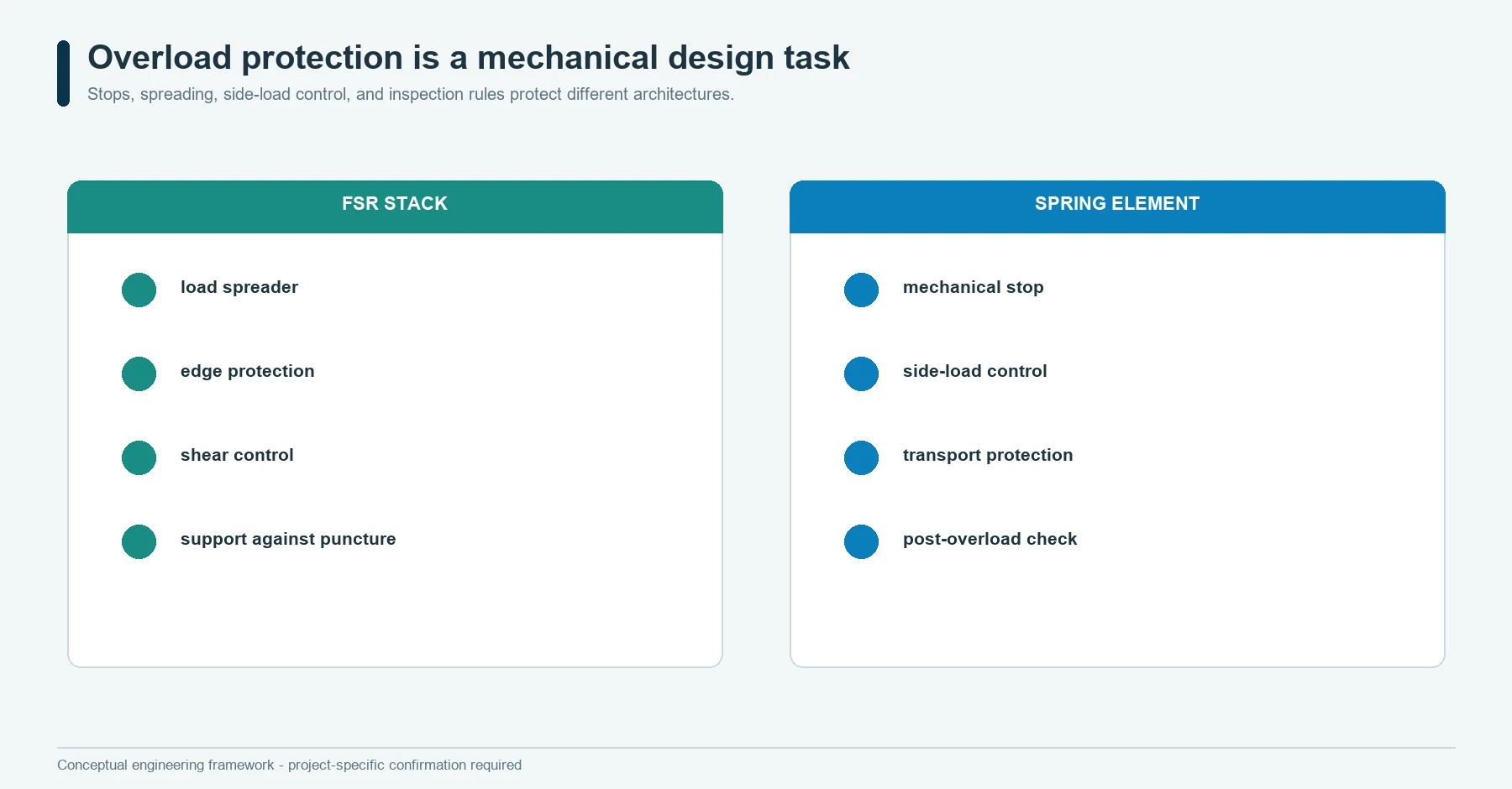
Software can detect an out-of-range output after overload begins. It cannot prevent a sharp boss from damaging an FSR or stop a spring element from exceeding its approved mechanical condition.
The FSR route may need:
- hard stops;
- controlled actuator travel;
- support that prevents puncture or sharp bending;
- edge and active-area protection;
- force-spreading geometry;
- shear control;
- handling and assembly limits.
The strain-gauge route may need:
- load stops;
- side-load and moment control;
- fastener and mounting limits;
- transport locks;
- protection from impact;
- cable-force isolation;
- inspection after overload.
An overload event can leave visible damage, a zero shift, a changed curve, altered hysteresis, or no obvious symptom. The service rule should state when the unit is rejected, rechecked, or recalibrated.
Thin Packaging and Low Cost Need a System Definition
FSRs are attractive when sensing must fit into a thin flexible region. That advantage can disappear if the product needs a complex actuator, precision support, environmental enclosure, individual calibration, or frequent replacement.
Strain gauges themselves are small, but a useful force transducer needs an elastic member, controlled load path, bridge wiring, protection, mounting, overload design, and instrumentation. Comparing gauge foil thickness with a finished FSR assembly is meaningless.
Compare total installed scope:
- sensor or gauges;
- designed mechanical converter;
- machining, forming, bonding, and protection;
- actuator, support, fasteners, and stops;
- cable and connector;
- analog front end and ADC;
- calibration equipment and time;
- production verification;
- rework and replacement;
- field recalibration;
- change qualification.
There is no universal cost, size, lead-time, or range winner. The system that needs less mechanical control on paper can demand more calibration and troubleshooting in production.
Failure Signatures Point to Different Owners
Use the observed pattern to direct investigation:
| Observed result | FSR first checks | Strain-gauge first checks |
|---|---|---|
| output changes with load position | contact patch, support, active-area alignment, bypass | load introduction, eccentricity, moment, mounting |
| zero changes after assembly | preload, foam, adhesive, cover compression | mounting strain, fasteners, cable, bridge balance |
| output moves during constant load | FSR creep, foam, adhesive, circuit | spring, bond, protection, mounting, electronics |
| high unit-to-unit spread | sensor, stack, actuator, assembly, calibration | spring geometry, gauge installation, bridge, calibration |
| temperature shifts output | sensor and stack materials, circuit | gauge compensation, spring material, mounting, electronics |
| response changes after overload | active area, layers, stop, support | spring element, stops, gauge bond, zero and span |
| noise increases in product | cable, leakage, supply, ADC, moving contact | shielding, grounding, excitation, amplifier, cable |
| calibration works only in fixture | fixture/contact mismatch | mounting/load-path mismatch |
These signatures do not prove root cause. They provide a disciplined first owner and preserve evidence before someone changes software or recalibrates over a mechanical fault.
Use a Measurement Contract to Select the Architecture
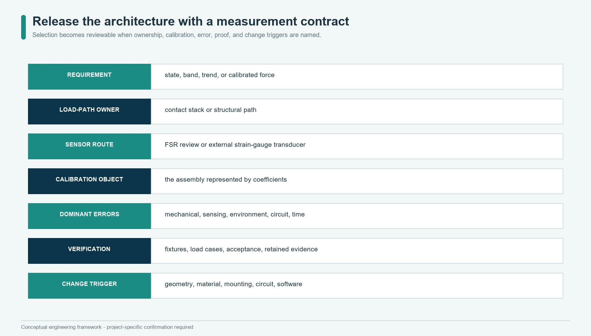
Release the technology decision with this record:
Requirement | Load-Path Owner | Sensor Route | Calibration Object | Dominant Error | Verification | Change Trigger
Example decision questions:
- Is the output a state, relative band, process trend, or calibrated force?
- Does load arrive through a local contact or a controlled structural path?
- Can the product include a dedicated elastic member?
- Must the sensor conform to a flexible or distributed surface?
- Which component is allowed to creep or deform?
- Who owns actuator, support, spring element, mounting, electronics, and calibration?
- Is field replacement expected?
- Does a replacement require recalibration?
- Which changes can shift zero, span, threshold, or classification margin?
- What evidence is required after overload, temperature exposure, or assembly change?
For automotive applications, the sensor result is only one input to the complete seat or vehicle system. The OEM or system integrator remains responsible for classification logic, diagnostics, warning behavior, safety analysis, compliance, and vehicle-level validation.
When Neither Route Fits
Choose another architecture when:
- only an open or closed state is needed and analog force information adds no value;
- load is distributed over a large area and a multi-zone mat provides the required pattern more directly;
- the structure cannot provide a controlled FSR contact or a controlled strain-gauge load path;
- the required output is pressure distribution rather than total or local force;
- the measurement must be isolated from the current mechanical stack;
- the environment, service plan, or overload cannot be controlled by either proposed construction;
- a commercial force transducer already solves the range, mounting, calibration, and documentation requirement better than a custom design.
The correct result may be a contact mat, capacitive or optical sensor, piezoelectric route, hydraulic or pneumatic method, commercial load cell, or a combined system. This article does not qualify those alternatives; it keeps the FSR and strain-gauge choice from being forced where neither owns the load path.
Frequently Asked Questions
Is a force sensing resistor the same as a strain gauge?
No. An FSR is a force-sensitive resistive element whose result depends on its contact stack. A strain gauge detects deformation on an elastic member and normally becomes useful for force measurement as part of a complete bridge-based transducer.
Which technology is better for a thin flexible interface?
An FSR is often the stronger starting route when the sensor must remain thin and the contact mechanics can be controlled. The choice still depends on the required output, calibration object, environment, and allowed variation.
Does JASPER supply strain-gauge load cells?
No strain-gauge load-cell product is claimed by this JASPER resource. The commercial JASPER route discussed here is a custom FSR-type sensor review, subject to project confirmation.
Can an FSR be calibrated to estimate force?
It can be characterized with the approved actuator, support, circuit, assembly, load history, and conditions. That relationship should not be transferred to a different contact stack without validation.
Why can the same force produce different FSR readings?
Contact area, alignment, hardness, foam, preload, support, shear, and load bypass can change how the total force reaches the active region.
When is a strain-gauge transducer the stronger route?
It is a stronger starting point when the product can route load through a designed elastic member and needs a calibrated structural force relationship with controlled mounting and instrumentation.
What should an OEM send for technology selection?
Send the load path, contact geometry, mechanical envelope, required output, range of operating states, circuit boundary, environment, overload cases, calibration object, validation plan, and quantities.
Sources
- Interlink Electronics,
FSR 400 Series, official manufacturer product page: https://www.interlinkelectronics.com/fsr-400 - Interlink Electronics,
FSR 400 Series Integration Guide, official manufacturer PDF: https://www.interlinkelectronics.com/downloads/integration-guides/fsr-400-series-integration-guide.pdf - Tekscan,
Embedded Force Sensors, official manufacturer product and integration overview: https://www.tekscan.com/products-solutions/embedded-force-sensors - Tekscan,
Load Cell vs Force Sensor, official manufacturer technical comparison: https://www.tekscan.com/resources/whitepaper/load-cell-vs-force-sensor - Tekscan,
How Do I Calibrate My FlexiForce Sensor?, official manufacturer support guidance: https://www.tekscan.com/support/faqs/how-do-i-calibrate-my-flexiforce-sensor - HBK,
Force Transducers Based on Strain Gauges, official manufacturer technical article: https://www.hbkworld.com/en/knowledge/resource-center/articles/force-transducers-based-on-strain-gauges - HBK,
What Is a Load Cell and How Does a Load Cell Work?, official manufacturer technical article: https://www.hbkworld.com/en/knowledge/resource-center/articles/what-is-a-load-cell-and-how-does-a-load-cell-work - HBK,
The Wheatstone Bridge Circuit, official measurement-technology article: https://www.hbkworld.com/en/knowledge/resource-center/articles/wheatstone-bridge-circuit - HBK,
Temperature Compensation of Strain Gauges, official manufacturer technical article: https://www.hbkworld.com/en/knowledge/resource-center/articles/article-temperature-compensation-of-strain-gauges1 - Micro-Measurements,
Strain Gage Sensor Reference Guide, official manufacturer selection and application guide: https://docs.micro-measurements.com/?id=8690 - National Institute of Standards and Technology,
Calibration of Force Transducers: https://www.nist.gov/programs-projects/calibration-force-transducers - ASTM International, ASTM E74,
Standard Practices for Calibration and Verification for Force-Measuring Instruments: https://store.astm.org/e0074-18r26.html - International Organization for Standardization, ISO 376,
Metallic Materials - Calibration of Force-Proving Instruments Used for the Verification of Uniaxial Testing Machines: https://www.iso.org/standard/44661.html
Send the Load Path and Evidence Plan
Use JASPER’s contact page to submit:
- application and required decision;
- source load and direction;
- minimum, normal, maximum, preload, dwell, and rate descriptions;
- contact area or structural load-introduction drawing;
- available envelope and permitted compliance;
- support, foam, actuator, spring, fastener, and enclosure details;
- target output and electronics boundary;
- calibration object and replacement strategy;
- environment, overload, lifecycle, and fault requirements;
- prototype and annual quantities;
- required evidence and change-notification rules.
For the validation record, JASPER’s quality and testing page provides a framework for connecting requirement, specimen, method, result, acceptance, and record. A prototype review should resolve the load path before production geometry or calibration coefficients are frozen.
JASPER can review whether a custom FSR construction fits the thin flexible sensing requirement. If the decision requires a strain-gauge transducer, the project needs a supplier and engineering scope that owns the spring element, gauge installation, bridge, calibration, and force traceability.