
PRODUCT KNOWLEDGE
What Is a Medical Electrode Pad?
A medical electrode pad is an electrical interface between a medical device and the body. Depending on its intended use, it may acquire physiological signals, deliver electrical stimulation or provide a return path for electrosurgical energy. Its conductive pattern, contact layer and connection must be designed for that specific function; a similar shape does not make different electrodes interchangeable.
Read the guide ↓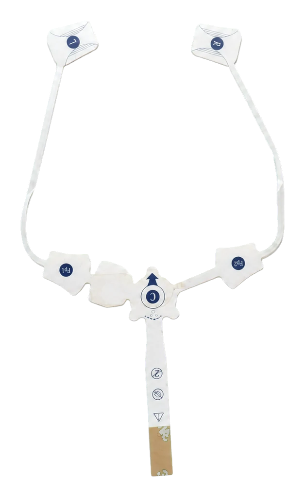
In this guide
- What does a medical electrode pad do?
- Recording, stimulation and return electrodes are different
- The layers inside an electrode pad
- Five printed-electrode product routes
- What are medical electrode pads made from?
- Connections need more than a connector name
- Which specifications matter when selecting a pad?
- How printed electrode components are manufactured
- Biological evaluation, packaging and device validation
- How to prepare an electrode-pad RFQ
- Frequently asked questions
What does a medical electrode pad do?
An electrode connects the device’s electronic circuit to a biological interface. A pad is the physical construction that supports that connection: it may combine a conductive element, carrier, contact medium, adhesive, liner and termination. Some supplied parts are complete contact assemblies. Others are printed circuit components that still require additional layers and device integration.
For an OEM, this distinction comes before material selection. A drawing for a printed electrode circuit is not a specification for a finished clinical accessory. Identify which layers the supplier delivers and which performance decisions remain with the device team. The medical electrode pad product family covers custom printed electrode components and project-defined assemblies rather than one universal pad.
A pad also differs from the electronics that interpret or generate a signal. It does not, by itself, diagnose a condition, control stimulation output or establish the safety of the complete system. A connector that fits mechanically is only one part of compatibility. Electrical function, contact construction, intended use and the receiving device must agree.
This guide addresses component selection and procurement. Clinical placement, treatment settings and use instructions belong to the approved device documentation and the responsible clinical team.
Recording, stimulation and return electrodes are different
The word electrode describes several functions. Start with the function, not the photograph or pad diameter. Three pads can look similar while requiring different materials, electrical tests and system interfaces.
| Electrode function | Purpose in the system | What the engineering review must distinguish |
|---|---|---|
| Physiological recording | Couple a body-surface signal to measurement electronics | Signal interface, noise, contact stability and lead connection |
| Electrical stimulation | Couple the prescribed device output to the body | Intended stimulator compatibility, contact construction and output-related validation |
| Electrosurgical return | Complete the intended return path to an electrosurgical generator | Generator compatibility, contact monitoring where applicable and the validated return-electrode design |
ECG and EKG are different abbreviations for electrocardiography, not different pad technologies. Recording electrodes acquire signals; their use must not be extended to stimulation merely because a lead can be attached. TENS and EMS belong to stimulation applications, but those labels alone do not establish interchangeability between accessories or devices.
An electrosurgical return electrode has a separate job. It returns electrosurgical current to the generator; describing it simply as an earth-ground sticker obscures that circuit function. A split contact pattern may relate to a particular monitoring system, but the appearance of a split is not proof of compatibility.
Defibrillation and pacing electrodes also require their own intended-use specifications. They are not substitutes for ordinary recording pads. These distinctions explain the broader terminology; they do not imply that every electrode function is a listed JASPER product route.
The layers inside an electrode pad
There is no mandatory stack-up shared by all medical electrodes. A gelled patch, dry-contact assembly and printed biosensor strip can have different layer arrangements. Review a cross-section alongside the circuit artwork so that an electrical area is not mistaken for an adhesive area.
| Element | Typical role | Drawing or specification question |
|---|---|---|
| Carrier or backing | Supports the geometry and handling | What material, thickness, outline and bend zones are required? |
| Conductive pattern | Defines contacts and carries signals or current | Which areas are exposed, insulated or connected together? |
| Contact interface | Couples the electrode to the intended surface or sample | Is the design gelled, dry-contact or an assay interface? |
| Adhesive and insulation | Position the assembly and separate selected regions | Are adhesive and conductive areas distinct or combined? |
| Release liner | Protects a removable adhesive or contact layer before use | How are the peel tab, split and removal sequence defined? |
| Termination | Connects the printed element to the device | Is the interface a tail, tab, snap, lead or other specified connector? |
Hydrogel can provide both electrical contact and adhesion in some constructions. In others, a separate adhesive border secures the patch while the conductive medium occupies a different region. Neither arrangement should be assumed from a product name.
The assembled stack changes how the part bends and how loads reach the conductor. A thin circuit can still develop a stiff region around a connector or reinforcement. Mark those transitions early, especially when a reusable electronics module connects to a disposable patch. A flat outline alone does not describe the mechanical interface.
Five printed-electrode product routes
The following routes describe different starting points for a custom project. They overlap: a wearable ECG patch can use an Ag/AgCl contact system, while a biosensor can share a printing process without sharing the same clinical function.
ECG / EKG electrode patches
ECG / EKG electrode patches are a route for body-surface recording interfaces. The component definition may include individual contacts or several electrode sites with printed routing. Contact location, connection assignment and the full contact-layer construction matter more than the outline alone. The complete recording system still determines signal interpretation and its acceptance requirements.
TENS / EMS electrode pads
TENS / EMS electrode pads belong to electrical stimulation programs. Their engineering review starts with the specified device and accessory requirements, then covers the conductive region, contact medium, lead or snap interface, and supplied assembly. Do not choose an area or material simply by assuming that a larger electrode or a more conductive ink is always better.
Wearable electrode patches
Wearable electrode patches combine flexible geometry with a body-worn product architecture. Bending, handling and the attachment of a module can influence the contact interface. The word wearable does not establish a wear duration, waterproof rating or reuse claim. Those properties need evidence from the complete construction under its intended conditions.
Ag/AgCl printed electrodes
Ag/AgCl printed electrodes identify a silver/silver-chloride material route, not one finished device category. The ink system, exposed region and intended contact chemistry must be specified together. An Ag/AgCl label is not evidence that two formulations, curing processes or interfaces will behave identically.
Printed biosensor electrodes
Printed biosensor electrodes provide electrode patterns for an electrochemical sensing system. A common arrangement uses working, counter and reference electrodes, but not every sensor has that configuration. Printed conductors alone do not provide analyte selectivity, calibration or a validated diagnostic result. Reagents, surface treatment, sample handling and the readout system remain part of the complete sensor design.
What are medical electrode pads made from?
Material selection is a coordinated choice across the stack, not a contest between isolated ink names. Flexible polymer carriers, printed conductors, insulating coatings, contact materials and adhesives each have a different job. A material suitable as an internal trace is not automatically suitable as an exposed contact.
Silver-containing inks can form printed conductors. Carbon systems can serve selected conductive or electrode roles. Ag/AgCl systems are used where their electrochemical behavior suits the intended interface. The applicable formulation and process must be identified; saying only silver, carbon or medical grade leaves too much undefined for repeat production.
Carrier selection includes dimensional stability during processing and flexibility in the finished geometry. Adhesive selection includes the actual contacting surfaces and required removal behavior. A strong bond on a test panel does not, on its own, answer whether the complete skin-contact assembly is appropriate for the intended use.
Require the material identity, supplier grade and relevant processing conditions in the controlled specification. A substitution can change more than conductivity: curing, adhesion, residual substances, flexibility and contact behavior may also change. Treat the finished construction as the evaluation unit where appropriate, rather than assuming that separate material datasheets add up to complete-device evidence.
Connections need more than a connector name
The interface between pad and device is both electrical and mechanical. A printed tail may need controlled contact orientation and reinforcement. A snap requires a defined mating component and attachment method. A leaded assembly adds wire routing and strain-relief decisions. None should be specified only by a photograph.
| Connection route | Information to place on the drawing | Risk to review |
|---|---|---|
| Exposed printed tail | Contact count, pitch, orientation and reinforcement | Wrong contact order or conductor damage at the bend |
| Connection tab | Contact geometry, accessible face and mating method | Unstable contact or load concentrated at the tab root |
| Snap connection | Mating interface and attachment construction | Mechanical fit without verified electrical compatibility |
| Attached lead | Conductor assignment, length and strain relief | Pull load reaching the pad or an intermittent connection |
Define where the connection is supported during assembly and use. A continuity result taken while the part lies flat will not reveal every problem introduced by movement or handling. Conversely, a bend check without a stated bend condition is difficult to repeat.
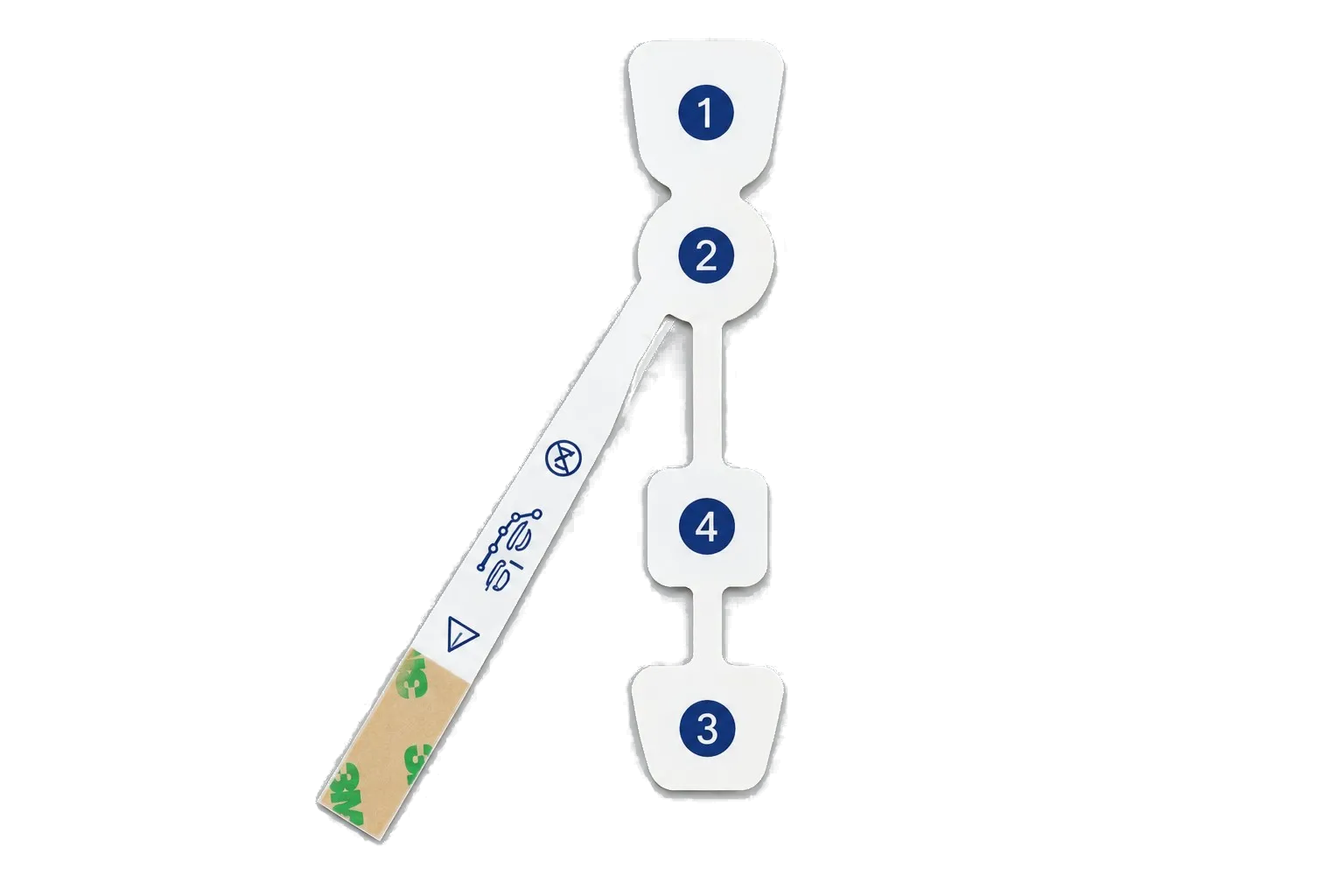
Where a device uses multiple electrode sites, document the connection map explicitly. The number of exposed contacts, electrode sites and measurement channels need not be identical. Their relationship comes from the system architecture, not from counting visible circles in a product image.
Which specifications matter when selecting a pad?
A useful specification connects each measurable feature to its function. Separate the conductor’s resistance from the impedance of the complete electrode interface. They are not the same measurement. State the test method and conditions whenever a number becomes an acceptance criterion.
For a recording design, the device team may evaluate electrical interface behavior, noise and stability alongside mechanical contact. For a stimulation design, the applicable output and accessory requirements must guide evaluation. A biosensor adds electrode configuration and assay-related requirements. One generic pass value cannot cover all three.
| Requirement group | What to define before sampling | What not to infer |
|---|---|---|
| Geometry | Active region, trace route, outline and datums | A larger area is automatically suitable |
| Electrical | Measurement method, conditions and acceptance limits | Low trace resistance proves a complete skin interface |
| Mechanical | Bend zones, connector support and handling conditions | A flexible film makes every assembled region equally flexible |
| Contact and adhesion | Intended interface, contact duration and evaluation conditions | More adhesive strength means better overall performance |
| Packaging and storage | Supplied condition, protective layers and storage requirements | A sealed pouch proves sterility or a particular shelf life |
The procurement benchmark is completeness, not the highest advertised number. Before releasing a sample order, require four matched items: a controlled drawing, a defined material stack, an interface specification and an agreed acceptance plan. Unresolved items can remain engineering questions, but should not silently become production assumptions.
This approach also makes quotations comparable. A price for a printed circuit without gel, liner or connector cannot be compared directly with a finished assembly that includes those components and its agreed inspection scope.
How printed electrode components are manufactured
A typical printed-component workflow starts with circuit and layer artwork. Conductive and insulating patterns are deposited on the selected carrier, processed under the specified conditions, and converted into the required shape. Additional contact, adhesive, liner or connection elements are incorporated when they belong to the agreed supply scope.
Process order depends on the construction. A manufacturer may print in sheets or another controlled format, inspect features before lamination, and perform cutting or assembly at different stages. The important point is that the route preserves the intended exposed regions and connection geometry. Printing a good-looking shape is not enough.
Inspection should correspond to the drawing: missing print, bridges, exposed conductors, registration errors, damaged edges and misplaced connection features each deserve an explicit disposition. Electrical checks can verify the agreed circuit requirements. They do not replace evaluation of the complete contact interface or prove a clinical outcome.
Keep the approved sample tied to an artwork revision, material record and manufacturing route. If a later order changes the carrier, ink, adhesive or assembly method, identify the change before treating it as equivalent. A retained appearance sample helps with visual comparison; it cannot preserve every electrical or biological property of a previous batch.
Biological evaluation, packaging and device validation
Biological evaluation depends on the nature and duration of body contact, the materials and processing, and the intended use of the device. ISO 10993-1 provides a risk-management framework; its name is not a blanket certification that makes every pad suitable for every patient-contact application. The relevant assessment can use existing evidence, justified analysis and testing where needed.
Evaluate the actual supplied and finished constructions. A change in formulation, processing or sterilization can affect the evidence required. The device team must decide whether a test article represents the final product, including contact layers and any relevant residues. A supplier declaration for one constituent does not automatically answer that question.
Packaging and shelf life are separate engineering subjects. Define how the part is supplied, what the package protects, and the storage conditions associated with the product claim. For a gelled construction, retaining the specified contact-layer condition may be important; for another construction, different characteristics may govern. Do not assign a generic expiry period from the word electrode.
Likewise, sterile and non-sterile are specified supply conditions, not conclusions drawn from a clean-looking photograph. Product labeling and any sterilization claims require the appropriate supporting work. Component manufacturing approval, finished-device validation and market authorization are different decisions. Keep responsibility for each explicit in the project agreement.
How to prepare an electrode-pad RFQ
Begin with a short description of the device function and the component you need to purchase. A recording patch circuit, a stimulation contact assembly and an assay electrode pattern should not enter the same quotation request with only a diameter and quantity.
Include the outline drawing, circuit artwork, stack-up, exposed contact regions, connection map, material requirements and planned quantities. State whether the request covers a bare printed layer, a converted multilayer part or an assembly with a defined interface. Add the agreed test scope and identify who supplies any contact material, reagent, connector or packaging.
The device team should also identify relevant use conditions and the evidence expected from the supplier. Separate required records from assumptions about clinical performance. If a parameter is not yet settled, identify its owner and the sample evaluation that will resolve it. This is more useful than hiding the gap behind a broad medical-grade label.
When those inputs are ready, request a custom electrode quotation with the controlled files and acceptance requirements. The first engineering objective is a clearly bounded component that can be built, inspected and evaluated consistently within the intended device program.
Frequently asked questions
Is a medical electrode pad the same as a sensor?
Not necessarily. An electrode is the electrical interface; a sensor system may also need electronics, chemistry, signal processing and calibration. A printed electrode component can be one part of that system without independently producing a validated measurement or diagnostic result.
Can ECG electrodes be used as TENS or EMS pads?
Do not assume interchangeability. ECG electrodes are intended for recording, while TENS and EMS accessories serve stimulation systems. Similar dimensions or a connector that fits do not establish equivalent function, compatibility or validation. Selection must follow the specific device and accessory requirements.
Does every electrode pad contain hydrogel?
No. Some constructions include conductive gel or hydrogel; others use dry-contact structures or a different sample interface. Adhesion may come from the contact layer or a separate region. Specify the actual stack-up instead of assuming that every flexible electrode has the same layers.
What does Ag/AgCl mean?
Ag/AgCl means silver/silver chloride. It describes a material system used in selected electrode interfaces, not a complete device category or universal performance grade. The formulation, processing, contact chemistry and finished construction still need to match the intended application.
Are larger electrode pads always better?
No. Active area is a design input tied to the device function and validated interface, not a universal quality ranking. Changing it can affect geometry, contact behavior and the applicable evaluation. There is no general pad-area recommendation suitable for every recording, stimulation or other medical system.
Does ISO 10993 mean a pad is clinically approved?
No. Biological evaluation addresses specified biological risks in the context of the finished device and its intended contact. It does not establish electrical compatibility, clinical performance, sterility or market authorization. Relevant evidence and responsibilities must be defined for the particular product.
Can a printed electrode pad be reused?
Reuse is a product-specific claim. It depends on the complete construction, intended use, handling or reprocessing requirements and supporting validation. A durable carrier or an adhesive that still feels tacky does not, by itself, establish an acceptable reuse life.
What should an OEM send for a custom electrode pad?
Provide the intended component function, controlled drawings, conductive artwork, layer construction, contact areas, connection details, material requirements, quantities and acceptance plan. State exactly what the supplier must deliver and which device-level evaluations remain with the OEM team.