
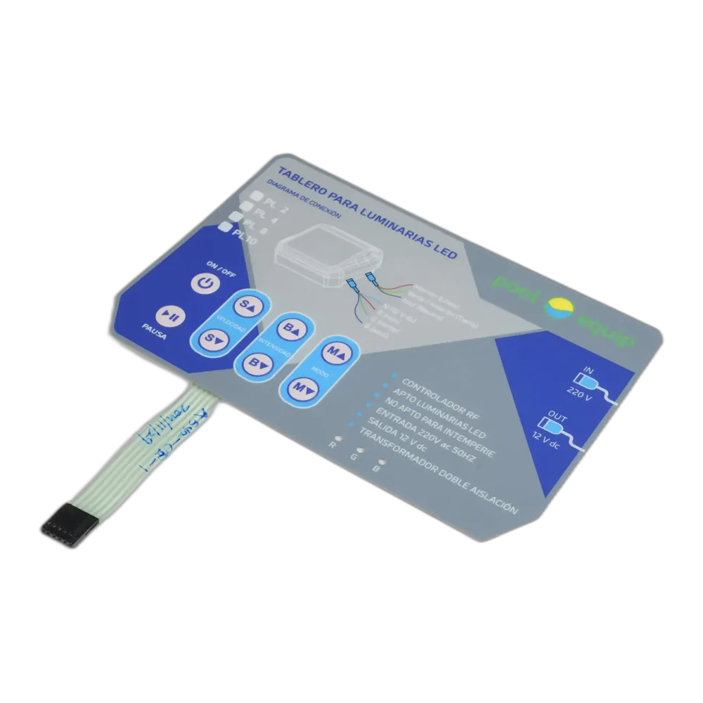
Waterproof Outdoor Membrane Switch for Harsh Environments
Waterproof membrane switch performance depends on the full assembly, not only the switch. The overlay, adhesive, gasket, tail exit, enclosure, venting, connector area, and validation test plan must work together.
JASPER can review the switch structure, housing interface, adhesive path, tail route, and target exposure before sampling, while treating IP ratings as project validation targets rather than automatic promises.
What the project needed to solve
The snapshot keeps the case practical: application, part type, design risks, and review scope.
| Item | Project direction |
|---|---|
| Application | Outdoor equipment, marine equipment, access control, or exposed industrial panel |
| Product type | Waterproof membrane switch or sealed control panel overlay |
| Key concerns | Moisture, UV exposure, temperature change, enclosure sealing, adhesive bonding |
| JASPER review scope | Waterproof structure review, material selection, gasket and tail design review, inspection |
| Project reference | JASPER project example |
A switch can be well made and still leak if the assembly is not reviewed
Outdoor and marine-adjacent equipment may face rain, condensation, sunlight, cleaning, vibration, and temperature change. A switch can be well made but still leak if the enclosure, adhesive contact surface, gasket compression, or tail exit is not properly designed.
IP65, IP67, and similar ratings should be treated as project targets that require structure review and validation at the assembly level.
Buyer note: Send the housing drawing, mounting surface, tail route, target exposure, and intended test method before finalizing the waterproof structure.
Design decisions JASPER would review before sampling
The response focuses on structure and production controls, not unsupported performance promises.
Water path review
Review edges, windows, screw holes, tail exit, connector area, gasket compression, enclosure gaps, and possible capillary paths.
Material and adhesive choice
Match overlay film, adhesive, ink stack, and backing material to UV, cleaning, temperature, and housing surface conditions.
Tail and connector protection
Plan tail exit direction, bend radius, strain relief, and connector location so the weakest point is not outside the sealing strategy.
Assembly-level validation
Define the target IP or cleaning test method and confirm whether the test applies to the switch alone or finished assembly.
Sample inspection
Check edge condition, adhesive contact, dimensions, electrical function, and visual quality before waterproof testing.
Inspection points that should be defined before approval
The sample should be judged against agreed visual, functional, dimensional, and documentation criteria.
| Area | Review point | Why it matters |
|---|---|---|
| Overlay | Outdoor durability, surface finish, print protection, UV exposure | Protects graphics and surface life |
| Adhesive | Bonding to metal, plastic, coated surfaces, or textured housings | Controls edge and mounting-surface sealing |
| Sealing | Gasket path, edge design, tail exit, enclosure fit, venting risk | Addresses real water entry paths |
| Circuit | Tail protection, connector location, moisture-sensitive areas | Reduces electrical failure risk |
| Validation | IP target, customer test method, assembly-level review | Prevents unsupported waterproof claims |
Information JASPER needs for a similar project
Better RFQ inputs reduce quotation back-and-forth and prevent late structural changes.
| Input needed | Useful detail | Why it matters |
|---|---|---|
| Enclosure drawing | Mounting surface, gasket area, screw positions, tail exit, connector cavity | Defines whether the sealing path is realistic |
| Target exposure | Rain, washdown, immersion target, UV, chemicals, temperature range | Drives material and validation choices |
| IP target | IP65, IP67, cleaning test, or customer-specific test method | Clarifies whether validation is switch-level or assembly-level |
| Tail and connector details | Exit direction, length, bend radius, connector location, strain relief | Prevents leakage and installation conflict |
| Mounting surface | Metal, plastic, powder coat, texture, curvature, adhesive area | Affects adhesive selection and bond reliability |
Buyer takeaway
Waterproof membrane switch design should begin with the enclosure. Send the housing drawing, mounting surface, tail route, and target IP expectation before finalizing the switch structure.
Continue planning this type of project
Related resources connect the case example with product options, resource guides, quality planning, and quotation preparation.
Questions buyers ask before sharing a similar project
Can JASPER make waterproof membrane switches?
Yes. JASPER can review waterproof membrane switch structures for outdoor, marine-adjacent, industrial, and related applications.
Does the membrane switch alone determine the IP rating?
No. The final IP result depends on the switch, adhesive, gasket, enclosure, tail exit, connector protection, and test method.
Should I send the enclosure drawing?
Yes. The enclosure drawing is important for adhesive, gasket, tail, and sealing review.
Can this case prove IP65 or IP67 performance?
No. This case explains design review logic. IP targets must be validated on the specific assembly and test method.
What is the common waterproofing mistake?
Treating the switch as waterproof while ignoring the enclosure surface, tail exit, connector, gasket compression, and installation method.
Need a waterproof membrane switch for outdoor equipment?
Send your enclosure drawing, target exposure, mounting surface, tail route, and target IP requirement for waterproof structure review.
Request Project Review