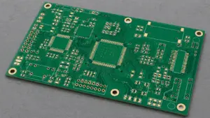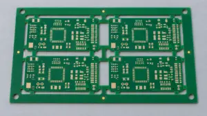
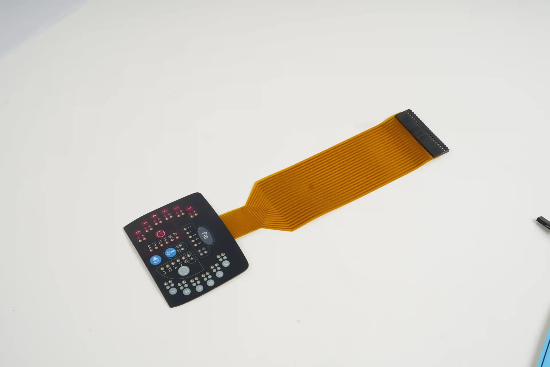
Across the 1,500+ custom HMI and membrane switch DFM (Design for Manufacturing) reviews our engineering team conducts each year, nearly 1 in 5 first-time prototype holds stems from a single mechanical oversight: mirror-image pinout reversals between the flexible membrane tail and the mating ZIF (Zero Insertion Force) connector on the host PCB. Because a membrane switch is drawn looking down at the front graphic overlay while the PCB footprint is often laid out looking down at the component side on the opposite face of an aluminum or plastic enclosure, folding the flexible tail 180° through a chassis slot flips Pin 1 to Pin N unless both teams define the contact orientation identically.
When you design custom membrane switches or PCB/FPC membrane switches, getting the tail interface right on the first build requires three specifications: unambiguous Top-Contact vs. Bottom-Contact pin numbering, a precision 0.30 mm ± 0.03 mm polyimide (PI) stiffener stack-up, and a carbon-passivated contact surface that resists fretting oxidation. This engineering guide walks you through the exact tolerances and CAD callouts our production team uses to guarantee plug-and-play mating on your very first prototype.
1. The 3D Geometry of Mirror-Image Pinout Reversals
In a typical industrial or medical enclosure, the membrane switch adheres to the exterior front recess of the housing, while its flexible PET or polyimide tail passes through a milled slot to mate with a right-angle or vertical ZIF socket on the main PCBA. The confusion arises because the exposed conductive fingers on the tail are single-sided (Single-Sided Exposed Contacts), covered on the opposite face by an insulating polyester film and a rigid polyimide stiffener.
If your schematic defines Pin 1 on the left edge of the tail when viewing the front graphic overlay face-up, and the tail then makes a single 90° bend straight down into a vertical ZIF connector, Pin 1 remains on the left. However, if the tail makes a 180° U-turn fold to plug into a right-angle SMD ZIF connector mounted on the rear side of the PCB, two things change simultaneously: the exposed conductive pads now face the opposite direction (Top-Contact vs. Bottom-Contact), and the physical left-to-right pin order reverses from 1–2–3…N to N…3–2–1.
- Define Contact Side Relative to the Front Overlay (‘Component View’): On your mechanical drawing, explicitly label whether the exposed silver/carbon ZIF fingers face UP (toward the viewer looking at the front graphic overlay) or DOWN (toward the rear 3M adhesive side) when the tail is laid completely flat (0° unfolded state).
- Physically Mark ‘PIN 1’ on Both the Tail Artwork and the PCB Silkscreen: Always instruct the factory to screen-print a bold PIN 1 triangle (▲) directly on the tail coverlay next to the first conductor, matching the Pin 1 chamfer on your PCB ZIF socket.
- Include the Exact Mating Connector Part Number on the Drawing: Listing the exact TE Connectivity, Hirose, or Würth ZIF part number (for example, specifying whether it is a 1.00 mm pitch bottom-contact or dual-contact socket) allows our CAM engineers to verify 3D mating orientation during pre-tooling review.
2. Standardizing the 0.30 mm ± 0.03 mm ZIF Mating Thickness Stack-Up
Even when the pinout order is correct, a flexible tail will fail intermittently under vibration if its mating thickness falls outside the ZIF actuator wedge tolerance. Both 1.00 mm pitch and 0.50 mm pitch SMD ZIF connectors ( as well as 2.54 mm clincher/crimp housings) are mechanically engineered around an industry-standard 0.30 mm ± 0.03 mm (0.012 in ± 0.001 in) total insertion thickness.
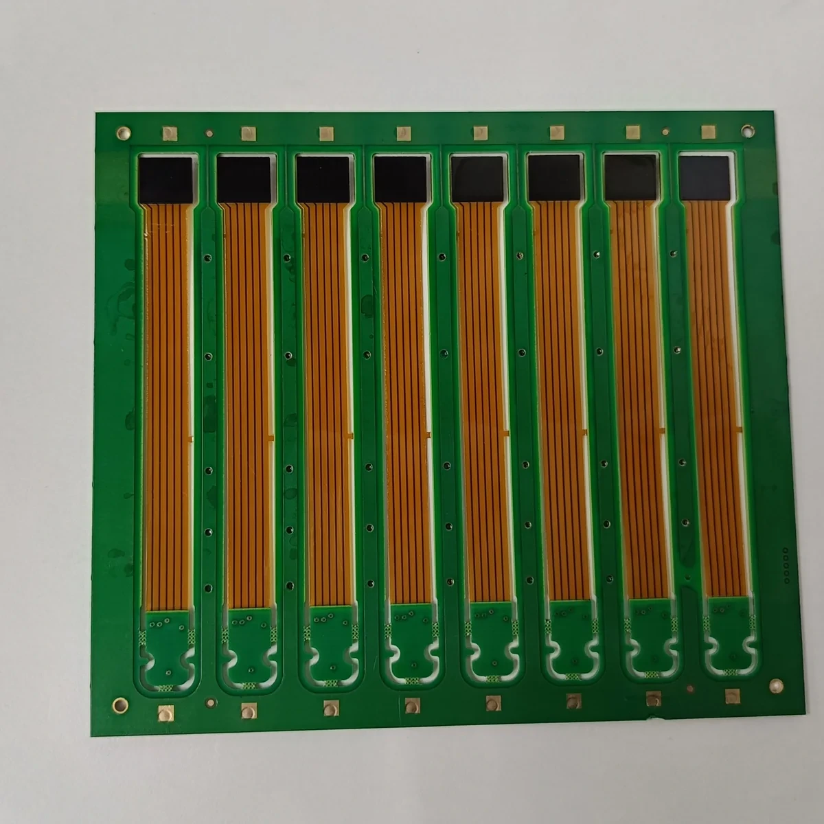
Because a bare heat-stabilized polyester (PET) circuit layer is only 0.100 mm to 0.125 mm thick—and a bare polyimide (FPC) copper circuit is even thinner at 0.050 mm to 0.075 mm—inserting an unreinforced tail into a ZIF socket results in zero normal contact force. As detailed in our Membrane Switch Design Guide, JASPER laminates a precision-calibrated blue or amber Polyimide (PI) or Polyester Stiffener onto the non-conductive back of the tail tip according to the exact stack-up table below:
|
Tail Interface Parameter |
1.00 mm Pitch ZIF (PET Silver/Carbon Tail) |
0.50 mm / 1.00 mm Pitch ZIF (Copper FPC Tail) |
2.54 mm Pitch Crimp / Berg Housing |
|
Total Mating Thickness ( |
|
|
|
|
Exposed Finger Length ( |
4.0 mm – 5.0 mm (±0.20 mm laser/die registration) |
3.5 mm – 4.5 mm (±0.10 mm photolithography etching) |
Pre-crimped female receptacle housing or male solder pins |
|
Stiffener Extension Length ( |
6.0 mm – 8.0 mm (extends |
5.5 mm – 7.5 mm (overlaps copper coverlay by >= 1.5 mm for strain relief) |
8.0 mm – 10.0 mm behind housing strain-relief latches |
|
Contact Surface Metallurgy |
Conductive Carbon Paste Over Silver Ink (prevents silver migration & fretting) |
Immersion Gold ( |
Tin-lead-free or selective gold-plated phosphor bronze terminals |
|
Minimum Tail Bend Radius ( |
>= 1.5 mm static single fold (>= 3.0 mm if folded near housing slot) |
>= 1.0 mm static fold (10× total flex thickness for dynamic flexing) |
>= 2.0 mm behind the rigid plastic connector housing |
Notice the critical relationship between Exposed Finger Length (4.0–5.0 mm) and Stiffener Extension Length (6.0–8.0 mm): the stiffener must always overlap the insulated UV dielectric coverlay by at least 1.5 mm to 2.5 mm. If the stiffener terminates at the exact same line where the dielectric insulation stops (0.0 mm overlap), it creates a sharp mechanical hinge right across the bare conductive fingers—causing the silver or copper traces to fracture the first time an assembly technician bends the tail.
3. Why Carbon-Over-Silver Passivation Is Mandatory Inside Tin-Plated ZIF Sockets
A frequent cause of field returns after 6 to 12 months in humid or thermally cycled environments is high contact resistance (>500 Ω) at the ZIF connector interface. When bare screen-printed silver ink (Ag) mates directly against a low-cost tin-plated (Sn) ZIF connector terminal, micro-vibrations wear away the soft tin oxide and trigger fretting corrosion, while ambient sulfur and moisture cause silver sulfide tarnishing (Ag2S) and dendritic silver migration between adjacent 1.00 mm pitch pins.
To eliminate ZIF contact degradation permanently, JASPER applies a dual-pass conductive carbon overcoat (10–15 µm thickness) directly over the silver contact fingers, and extends the UV-cured dielectric mask 1.0 mm inside the ZIF socket throat. The inert carbon layer shields the underlying silver from atmospheric oxidation, acts as a dry solid lubricant during repeated ZIF insertions, and prevents dissimilar-metal galvanic corrosion against tin or gold connector contacts.
|
Pre-RFQ DFM Checklist: 5 Rules for Zero-Defect Tail & Connector Integration • [ ] Add a 1:1 Unfolded Tail Pinout View With ‘PIN 1’ Clearly Marked: Always show whether the exposed contacts face the Front Overlay side or Rear Adhesive side before folding. • [ ] Stagger the Stiffener Edge and Coverlay Edge by >= 1.5 mm: Never align the end of the polyimide stiffener with the end of the dielectric insulation layer; overlap them to prevent trace cracking. • [ ] Widen the Enclosure Tail Exit Slot by ±1.0 mm Per Side: A 12.0 mm wide tail requires at least a 14.0 mm × 2.5 mm chamfered housing slot so assembly tolerances never pinch or shear the outer traces (see our Membrane Switch RFQ Checklist). • [ ] Never Crease a Silver-Ink Tail Over a 180° Hard Fold: Folding screen-printed silver ink flat against itself with a zero-radius crease cracks the polymer binder; maintain a >= 1.5 mm bend radius. • [ ] Consider a Dual-Contact ZIF Socket During EVT/DVT Prototyping: Specifying a top-and-bottom dual-contact ZIF receptacle on your Rev A prototype PCB protects your schedule against accidental pinout inversions. |
Frequently Asked Questions (FAQ)
Q1: What is the standard thickness of a membrane switch tail for a 1.00 mm pitch ZIF connector?
The industry-standard mating thickness for both 1.00 mm and 0.50 mm pitch ZIF connectors is 0.30 mm ± 0.03 mm (0.012 in ± 0.001 in). We achieve this by laminating a precision 0.150–0.175 mm polyimide (PI) or polyester stiffener onto the back of the 0.125 mm circuit tail.
Q2: Should I choose a 1.00 mm ZIF tail or a 2.54 mm pitch crimped female housing?
Use a 1.00 mm pitch ZIF tail for compact, automated SMT boards with low-profile enclosures where cost and PCB area are tight. Choose a 2.54 mm (0.100 in) pitch crimped female housing (with latching friction locks) for high-vibration industrial machinery, fitness equipment, or field-serviceable panels where technicians unplug and reconnect the harness repeatedly.
Q3: When should I upgrade from a printed silver PET tail to a copper FPC membrane switch tail?
Upgrade to a PCB/FPC Membrane Switch when your connector pitch is 0.50 mm, when the tail must carry high LED currents (>100 mA), when you need soldered SMD components (LEDs, resistors, blocking diodes) directly on the circuit layer, or when the tail must survive tight 1.0 mm radius bends.
Get a Free Pre-Tooling ZIF & Pinout DFM Review From JASPER
Before you lock your PCB layout or release Gerbers, send your enclosure STEP file and keypad pinout to our engineering team. We can review your 3D tail folding geometry, stiffener stack-up, and connector orientation, with the review scope and schedule confirmed for your project. Explore our Custom Membrane Switches or Request a Quote today.
Ready to Start Your Project?
Tell us about your membrane switch, keypad, or graphic overlay requirements. Our engineering team will review your specifications and provide a detailed quote.