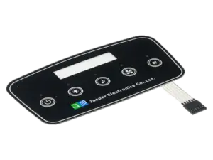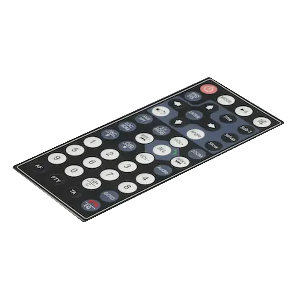

A waterproof membrane switch is a layered keypad designed for a specified ingress environment. Its IP rating depends on the tested configuration, including the keypad, sealing interfaces and enclosure to which it is fitted. A component’s reference test does not automatically qualify the customer’s complete product.
Mechanical teams should review the switch and housing together. A laminate that passes an ingress test on one fixture may not pass on another housing with different bond geometry, stiffness or installation. Important variables include sealing-land width, surface preparation, gasket compression and tail-exit geometry — all of which need coordinated design review before production.
1. Why IP Performance Depends on the Complete Assembly
A sealed membrane switch typically combines an overlay, circuit films, spacers and adhesive layers; the number, thickness and sealing layout vary. Perimeter adhesive, circuit encapsulation and tail construction all matter. Water can enter through a manufacturing defect, an unsuitable design, aging or installation damage. A breached laminate is therefore not automatically only a quality-control issue: investigate both design and process.
One important leakage route is the interface between switch and enclosure: the perimeter adhesive bond, tail slot or vent. IEC 60529 evaluates the specified enclosure configuration. IPX7 concerns temporary immersion under the standard’s conditions; depth is related to enclosure size and position, not an unrestricted underwater-use claim. Record the tested mounting, openings and seals, and validate the actual product rather than transferring a bare-component claim.
A useful principle for the OEM team is that waterproof design requires joint responsibility for enclosure and keypad. Agree ownership of adhesive selection, film alignment, seal continuity, housing finish, fastener loading and tail sealing. No fixed percentage of responsibility or universal land width and screw pitch guarantees IP67. Use tolerance analysis and representative testing to find weak points; both the keypad construction and its installation can contribute to failure.
2. Four Leakage Paths to Review
These four paths are a practical review framework, not an exhaustive list or a measured ranking of field failures.
| # | Leakage path | Mechanism | Design variables | Possible symptom |
|---|---|---|---|---|
| 1 | Perimeter adhesive bond | Bond lifting after incompatible exposure, stress or poor preparation | Land width, substrate compatibility, flatness and surface roughness; Ra is roughness, not flatness | Edge lift or water along the bond line |
| 2 | Gasket compression zone | Insufficient, uneven or excessive compression | Grade-specific compression range, fastener loading, gap tolerance and housing stiffness | Leakage at a low-pressure region |
| 3 | Tail / flex-circuit exit | Capillary paths along films, traces or an incompletely sealed opening | Slot shape, seal compatibility, strain relief and tail bend | Intermittent electrical faults after water exposure |
| 4 | Vent or pressure-equalization port | Liquid entry through an unsuitable vent or its mounting seal | Liquid-entry resistance, airflow, contamination and installation location | Moisture inside the panel or enclosure |
Any of these paths can matter at different IP levels. Their importance depends on pressure, exposure duration, thermal cycling, contamination and the actual design. Do not assume vent leakage occurs only at deep immersion or high-pressure wash ratings, or that fixing the perimeter automatically resolves the tail exit.
Adding adhesive or changing overlay material does not by itself qualify the assembly. Depending on the root cause, correction may involve the laminate, adhesive pattern, gasket, housing, vent or installation process. Recheck tactile function and electrical behavior after sealing changes, particularly where internal air movement affects dome response.
3. Enclosure Specifications to Define Before IP Testing
Specify sealing geometry and surface requirements on the drawing for the selected materials. IEC 60529 does not prescribe one land width, flatness, screw pitch or gasket squeeze for each IP class. The table is a design-review matrix: determine each value through supplier data, tolerance analysis and assembly testing.
| Housing parameter | IP54: splashing water | IP65: water jets | IP67: temporary immersion | IP68: agreed immersion conditions |
|---|---|---|---|---|
| Sealing land width | Define for the adhesive or gasket | Validate under jet exposure | Validate under temporary immersion | Validate at agreed depth and duration |
| Surface flatness and gap variation | Drawing tolerance | Include distortion under clamp load | Check worst-case installed gap | Include pressure and aging effects |
| Surface roughness for adhesive bonding | Match substrate and adhesive | Specify and validate finish | Specify and validate finish | Verify finish after exposure |
| Fastener arrangement and housing stiffness | Set by load and geometry | Verify continuous contact pressure | Check between fasteners | Verify pressure-load response |
| Gasket compression | Grade-specific range | Check minimum compression | Check full tolerance stack | Verify after conditioning |
Flatness and roughness are separate characteristics. A smooth but warped land can leave a sealing gap, while a flat surface may still be too textured or contaminated for the chosen adhesive. Specify both as needed, together with substrate, coating and cleaning process. Do not assume a casting, molding or tool-polish designation alone proves bond suitability or an IP result.
Fasteners create local clamp loads; the spans between them can have lower compression or higher distortion. Use the selected gasket’s compression-deflection and compression-set data, housing stiffness and tolerance stack to evaluate the minimum and maximum compression around the full perimeter. Confirm the analysis with representative parts after relevant aging. A single material test result is not a prediction of assembled seal recovery in every geometry.
The design principle is to develop the housing interface and keypad sealing footprint together. Resolve assembly access, serviceability, tactile venting and tail routing before releasing tooling. Prototype testing remains necessary; no drawing rule guarantees a first-pass IP67 result.
4. Selecting Gasket Materials
Adhesive-only and compression-assisted seals are both possible, but neither has an automatic IP ceiling. Select them for housing stiffness, gap tolerance, temperature, chemicals and service access. The 467MP and 468MP designations are examples of specific adhesive grades, not universal choices; check the current datasheet and actual substrates for any selected grade. Adding a gasket may require a pocket, compression stops and revised fastening; confirm the complete arrangement by testing.
| Material family | Compression data to verify | Temperature assessment | Chemical assessment | Ingress qualification | Cost basis |
|---|---|---|---|---|---|
| PORON microcellular urethane, selected grade | Check grade datasheet and test method | Use grade-specific limits | Check the actual fluids and exposures | Assembly test required | Quote selected grade |
| Solid silicone, selected compound and hardness | Compound-specific recovery data | Confirm continuous and peak conditions | Compatibility varies by compound and chemical | Test the installed seal | Quote compound and geometry |
| Closed-cell silicone sponge | Density and grade-specific data | Check grade and aging conditions | Verify swelling and property changes | No rating from material name alone | Quote density and thickness |
| Other polyurethane foams, grade-specific | Check chosen foam, not a generic value | Confirm selected grade limits | Check cell structure, fluids and UV exposure | Validate liquid blocking in the assembly | Compare qualified grades |
| Butyl-based sealing tape, selected product | Assess creep, flow and replacement needs | Check product-specific service limits | Confirm compatibility with fluids and substrates | Qualify the complete joint | Include replacement and assembly |
Select a grade using its compression behavior, recovery, liquid resistance and actual temperature/chemical exposure. PORON is itself a family of microcellular polyurethane materials, not the opposite of polyurethane foam. Silicone performance also depends on compound and geometry. If sterilization is required, validate the complete assembly against the specified cycle; IEC 60601-1 does not prescribe a universal 134 °C / 18-minute autoclave cycle for all reusable medical devices.
Do not predict a fixed service life or failure month from the generic label ‘PU foam’. Open-cell, closed-cell and engineered microcellular products differ, and installation conditions matter. Likewise, a butyl-based seal is not automatically suitable for repeated service or unsuitable for long life. Review supplier evidence, creep, reassembly and replacement instructions, then verify the intended design.
5. Verification Methods and Their Limits
Specify the tested assembly, method, edition, severity and acceptance criteria. IEC 60529 covers IP classification; tailored MIL-STD-810H environmental tests may be additional project requirements, not a universal replacement. Adhesive strength and gasket material tests support design decisions but do not independently establish enclosure ingress protection.
| Standard / method | What it evaluates | Conditions to define | Use in qualification |
|---|---|---|---|
| IEC 60529 IPX5 | Water jets | Specified nozzle, flow, distance and duration in the selected edition | When water-jet resistance is required |
| IEC 60529 IPX6 | Powerful water jets | IPX6-specific setup and exposure; not the IPX5 setup | When the specified use requires powerful jets |
| IEC 60529 IPX7 | Temporary immersion | 30-minute test with immersion geometry defined by the standard | Temporary immersion requirement |
| IEC 60529 IPX8 | Immersion under agreed conditions | Agreed depth, duration and other conditions meeting the standard | A defined immersion duty beyond IPX7 conditions |
| IEC 60529 IPX9 / ISO 20653 IPX9K | High-pressure, high-temperature water jets | Select the correct standard, code and complete test procedure | Specified high-pressure cleaning; vehicle requirements may use ISO 20653 |
| MIL-STD-810H Method 506.6 | Rain exposure | Project-tailored procedure, rainfall, wind, orientation and duration | When specified in the environmental qualification plan |
| ASTM D1002 | Apparent shear strength of bonded metal lap joints | Defined specimen and method; not a direct water-ingress test | Where relevant to the selected adhesive joint |
| ASTM D1056 | Specification and tests for flexible cellular rubber products | Applicable grade, specimen and test conditions; not one universal aging cycle | Relevant material characterization, followed by assembly validation |
Writing “IP67-rated” alone on a drawing leaves uncertainty about the test object and evidence. Identify the complete mounting arrangement, required standard edition, dust and water tests, conditioning, acceptance criteria and report requirements. For example: “Complete assembly in the specified mounting configuration to meet IEC 60529 IP6X and IPX7 under the approved test plan; report the setup, conditioning and results.”
6. Frequently Asked Questions
How do I design a waterproof membrane switch from scratch?
Define the actual water and dust exposure and required IP tests, then design the keypad and housing interface together. Specify substrate preparation, sealing footprint, flatness, gap tolerance, clamp load, gasket compression where used, tail routing and venting. Choose values from material data and tolerance analysis, then test representative assemblies. A universal 3 mm land or fixed screw pitch cannot guarantee IP67.
Why does the enclosure matter for an IP67 keypad?
The enclosure determines bond support, local gaps, clamp-load distribution and the routing of openings. Those features interact with the laminate, adhesive, gasket and vent. Either the component construction or installation can cause leakage. Qualify the combined assembly and assign clear responsibilities to both OEM and keypad supplier rather than assuming the laminate is always sound.
What gasket compression percentage is best?
Use the selected grade’s compression-deflection, recovery and aging data with the installed gap and tolerance stack. Verify minimum and maximum compression around the perimeter, including between fasteners and after conditioning. Solid silicone, silicone sponge and polyurethane grades do not share one universal percentage. Both inadequate compression and excessive crushing can compromise sealing or assembly behavior.
Can an existing membrane switch assembly be upgraded to IP67?
Possibly, but inspect all ingress paths before deciding what to change. The solution may involve adhesive preparation, laminate sealing, a gasket, housing geometry, tail exit or vent selection. Added sealing can affect tactile venting and serviceability. Test the modified assembly; neither an extra gasket nor an adhesive change alone proves IP67.
What flatness does the enclosure need for the seal?
Set a drawing tolerance that the chosen adhesive or gasket can accommodate throughout the actual assembly. Evaluate span, local waviness, surface texture, clamp distortion and aging. Ra measures surface roughness, not overall flatness; specify and measure them separately. There is no single flatness value in IEC 60529 that guarantees an IP67 perimeter seal.
How should the flex-circuit tail exit be sealed?
Options include compatible potting, a designed compression seal or a purpose-made flat-cable feedthrough. Check adhesion to the tail, cure compatibility, bend radius, strain relief, service access and capillary paths between layers. A gland qualified for round cable is not automatically suitable for a flat membrane tail. Qualify the selected exit as part of the finished assembly.
Does an IP67 result apply to the keypad or the assembly?
It applies to the configuration described in the test report. IP67 combines the dust requirement IP6X with temporary-immersion requirement IPX7; an IPX7 result alone is not full IP67 evidence. Review the housing, mounting, seals and conditioning used. Retest or otherwise substantiate the OEM’s actual configuration through the approved qualification process rather than automatically transferring a reference-housing result.
What field leakage symptoms should be investigated?
Investigate edge lift, moisture under the overlay, corrosion, intermittent keys and leaks near exits or fasteners. Check contamination, adhesive wet-out, seal continuity, mechanical strain, compression and environmental exposure. Do not assign a universal failure ranking or six-to-eighteen-month lifetime without field data. Preserve failed parts and correlate the leak path with the tested design and assembly records.
This guide is provided by JASPER Electronics, a custom membrane switch and keypad manufacturer. It supports design discussions and does not certify a material, component or enclosure to an IP rating. Validate the actual product with the agreed requirements and test evidence.
Ready to Start Your Project?
Tell us about your membrane switch, keypad, or graphic overlay requirements. Our engineering team will review your specifications and provide a detailed quote.