
CUSTOM PRINTED MEDICAL ELECTRODES
Custom Printed Medical Electrode Pads
JASPER is a medical electrode pad manufacturer for OEM teams that need custom flexible printed electrode circuits, converted layers, and assembly support built to a project drawing.
Geometry, substrate, conductive pattern, contact interface, tail, and connector are project-defined. Finished-device performance and regulatory validation remain with the customer program.
- Custom geometry
- Flexible printed circuits
- Prototype to repeat builds
PRODUCT BROCHURE
Medical Electrode Product Brochure
Review standard disposable neutral, ECG, and physiotherapy electrode examples, plus conductive adhesive, medical foil, carbon film, and electrode clip options. The brochure is a product overview; send the drawing and intended use for an engineered quotation.
SCOPE BEFORE SPECIFICATION
Printed electrode manufacturing, with the boundary made clear
Medical electrode projects combine a printed electrical structure with materials and validations that depend on the finished device. Separating those responsibilities at quotation stage keeps the BOM, evidence package, and approval plan honest.
JASPER can quote
- Customer-defined flexible conductive patterns
- Screen printing, die cutting, lamination, and conversion
- Project-specified adhesive, gel, liner, and contact layers
- Flexible tails, contacts, snaps, leads, and connector interfaces
- Prototype, sample approval, and repeat-build support
The device team validates
- Intended clinical use and electrode placement
- Patient-contact material and biocompatibility requirements
- Sterility, packaging, shelf-life, and disposal claims
- Electrical, mechanical, and clinical performance limits
- Regulatory submissions, labeling, and finished-device approval
PROGRAM ROUTES
Start with the electrode program closest to your design
These routes describe manufacturing conversations, not off-the-shelf medical devices. JASPER reviews the exact artwork, material stack, termination, test criteria, and customer-controlled claims before quoting.
01 / RECORDING
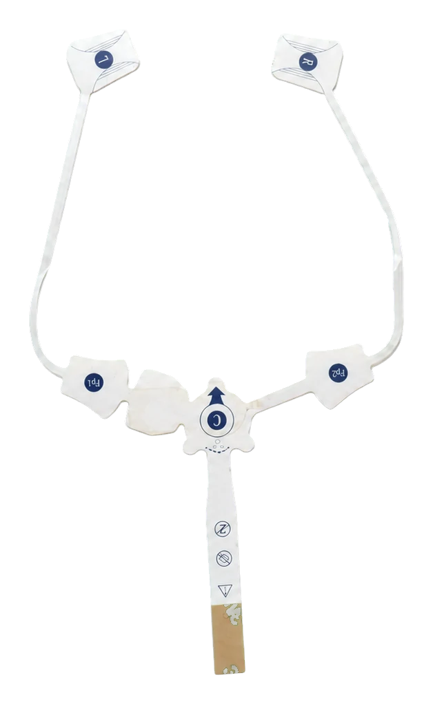
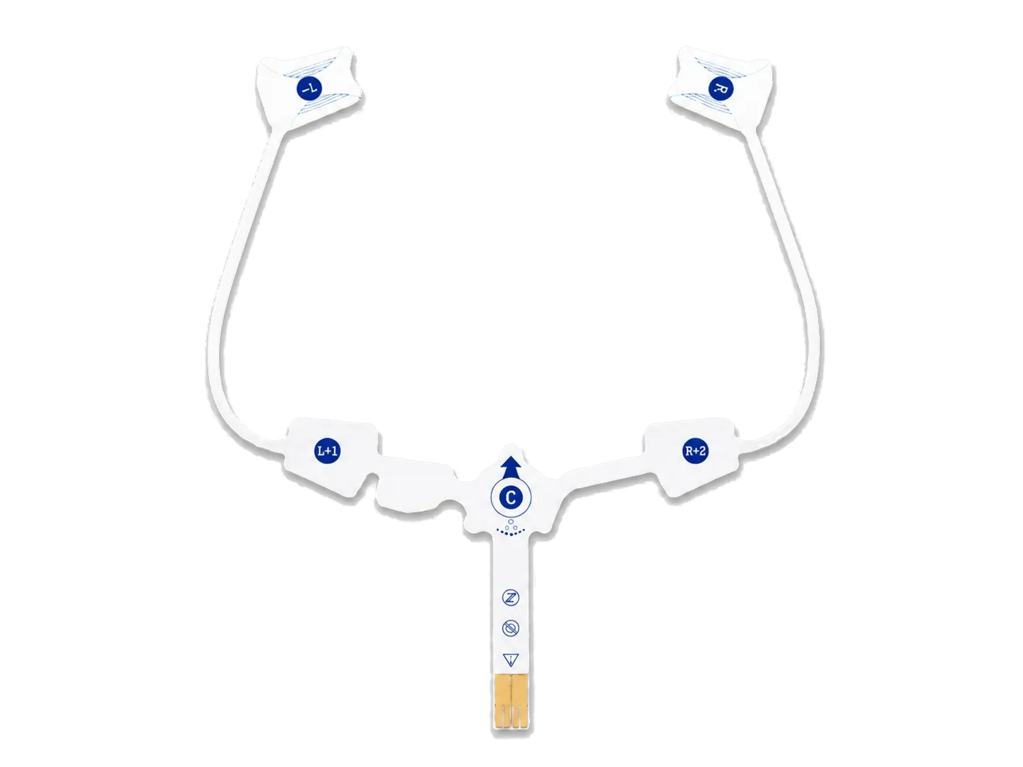
ECG / EKG electrode patch circuits
Single- or multi-site patterns, distributed contact areas, and integrated tails can be reviewed against the monitoring-system drawing.
02 / STIMULATION
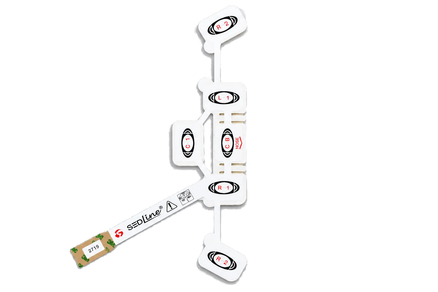
TENS / EMS electrode pad circuits
Custom pad geometry, lead or snap interface, liner, and project-defined contact layer can be quoted as an OEM construction.
03 / WEARABLE
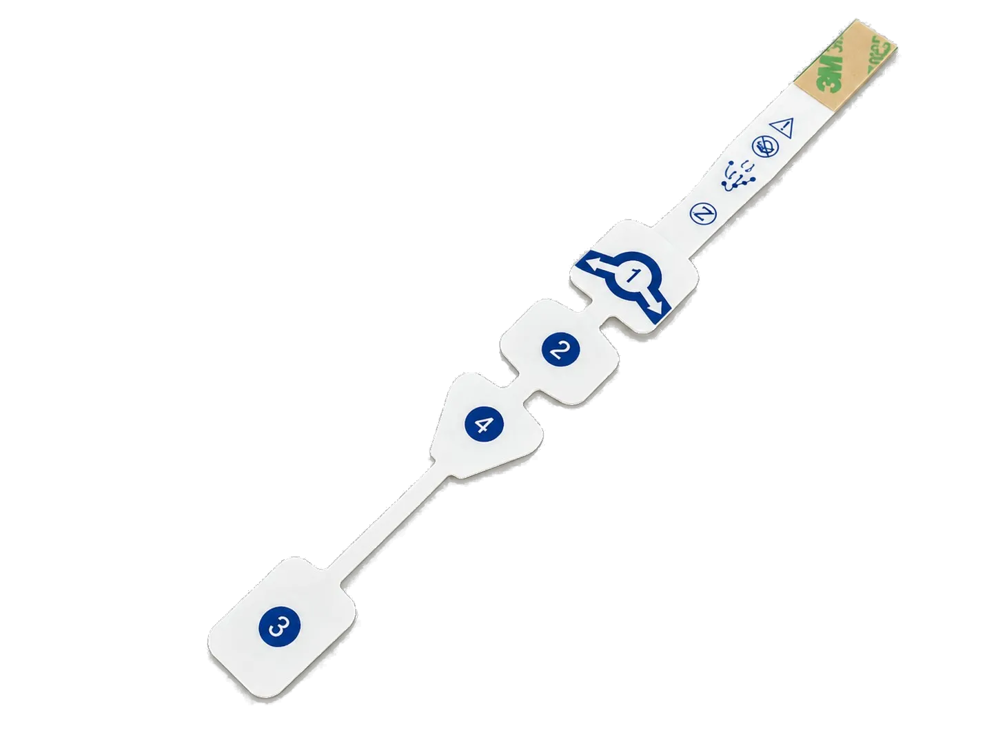
Wearable medical electrode patches
Body-worn flexible circuits can combine printed traces, distributed electrode locations, and compact termination zones for the customer’s patch stack.
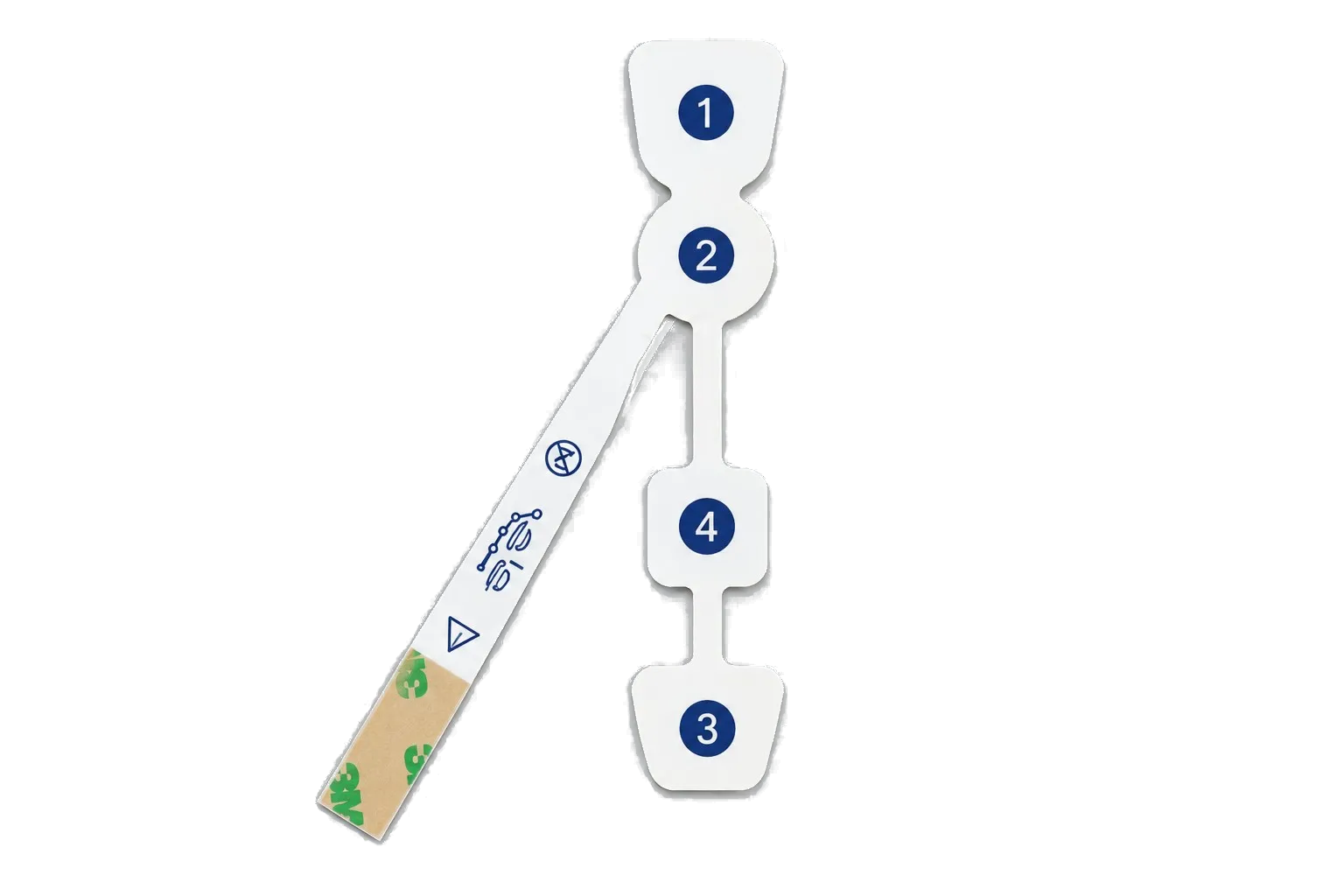
04 / CONDUCTIVE SYSTEM
Screen-printed Ag/AgCl electrodes
Ag/AgCl is one possible project-defined conductive system. Ink, interface chemistry, geometry, curing, and acceptance criteria must be confirmed for the exact design.
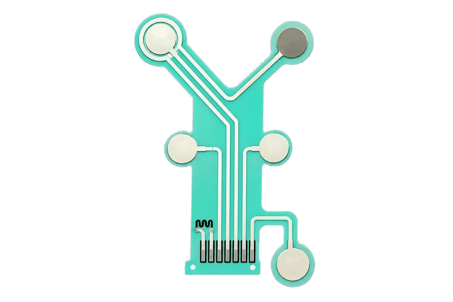
05 / SENSOR
Screen-printed biosensor electrodes
Working, counter, and reference electrode patterns, contact areas, and terminal layouts can be converted from customer-controlled artwork and test requirements.
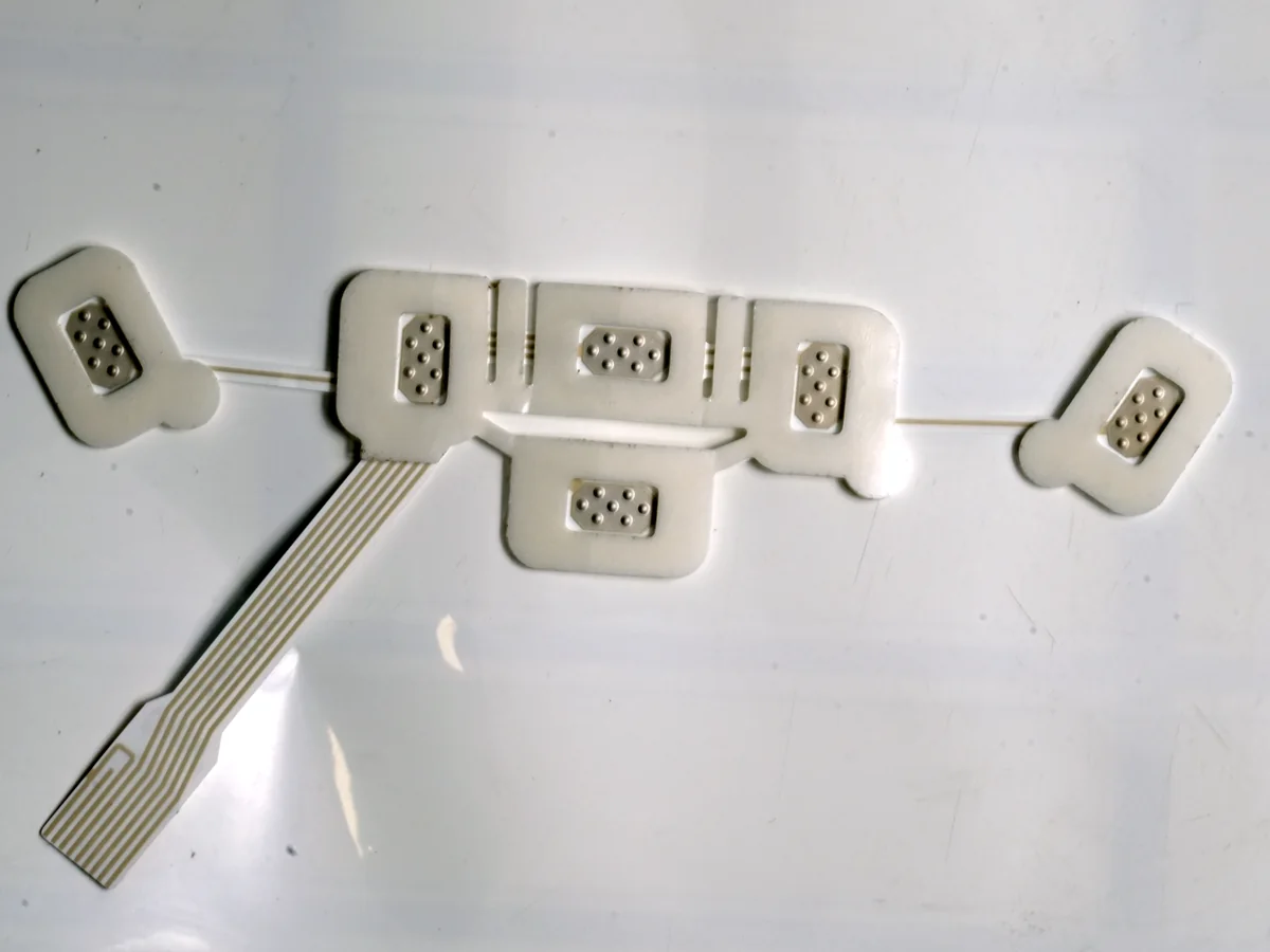
LAYER-TO-LAYER CONTROL
Specify the entire stack, not only the electrode shape
- 01Cover, liner, or positioning layer
Controls handling, placement, release sequence, and exposed areas.
- 02Adhesive or contact interface
Defined by skin, enclosure, sensor, or assembly requirements.
- 03Printed conductive layer
Electrode areas and traces follow the approved artwork and ink system.
- 04Dielectric and routing protection
Insulates selected traces while leaving specified contact areas accessible.
- 05Carrier, tail, and termination
Links the flexible pattern to the customer’s connector, lead, or electronics.
The actual sequence and materials vary by program. The customer-approved drawing and BOM remain the controlling documents.
PROJECT FLOW
From drawing review to repeat production
- 01
Define inputs
Share the electrode map, stack, materials, termination, tolerances, validation needs, and program phase.
- 02
Review manufacturability
JASPER checks printable geometry, registration, tail routing, conversion steps, and assembly interfaces.
- 03
Build prototypes
Samples are produced to the agreed revision and submitted for the customer’s functional and device-level evaluation.
- 04
Close validation
Customer feedback, material evidence, test results, and drawing changes are resolved before production release.
- 05
Control repeat builds
The released artwork, BOM, inspection plan, and approved sample become the basis for repeat manufacture.
ENGINEERING INPUTS
What to send for a useful quotation
A clear RFQ reduces assumptions and makes supplier responses easier to compare.
Send Your Electrode Drawing- 2D drawing with dimensions, datums, and tolerances
- Electrode map, channel count, and trace artwork
- Target substrate, thickness, and bend requirements
- Conductive and dielectric material requirements
- Contact layer, gel, adhesive, and liner specification
- Tail, snap, lead wire, connector, and mating details
- Operating, storage, packaging, and disposal requirements
- Inspection plan, acceptance limits, volume, and program phase
BUYER QUESTIONS
Medical electrode manufacturing FAQ
These answers describe JASPER’s manufacturing scope. The approved drawing, BOM, quality plan, and customer validation define the actual deliverable.
What types of printed medical electrodes can JASPER review?
JASPER can review project-defined ECG or EKG patch circuits, stimulation electrode circuits, wearable electrode arrays, Ag/AgCl printed patterns, and biosensor electrode layouts when the requested construction fits our screen-printing and converting capability.
Can the electrode geometry, substrate, adhesive, tail, and connector be customized?
Yes. Those are normal engineering inputs for a custom quote. The final combination must be controlled by the customer’s drawing, BOM, application requirements, and validation plan.
Does JASPER supply a finished electrode pad or only the printed circuit?
The deliverable depends on the quoted scope. It may be a printed circuit layer, converted multi-layer part, or a specified assembly. The RFQ should identify which materials and components are customer-supplied, nominated, or purchased by JASPER.
What information is required to quote an electrode pad?
Send dimensions, electrode map, artwork, stack, materials, contact interface, termination, tolerances, test criteria, expected volume, and program phase. Include regulatory or material-document requirements that affect sourcing.
How are Ag/AgCl, silver, and carbon systems selected?
They are selected against the electrode function, substrate, interface chemistry, printing process, curing limits, and electrical acceptance criteria. JASPER does not substitute one system for another without project approval.
Can JASPER support prototypes and repeat production?
JASPER can quote prototype and repeat-build stages when the construction fits our capability. Customer testing and drawing release are required before a prototype becomes an approved production definition.
Does the page claim FDA clearance, CE certification, or ISO 13485 status?
No. Those claims are not universal manufacturing attributes of the parts shown here. Any regulatory, quality-system, sterility, or patient-contact statement must be supported for the exact supplier, material, process, and finished device.
Who is responsible for finished-device validation?
The medical-device customer owns intended use, risk management, material and biocompatibility requirements, electrical and clinical performance, labeling, regulatory submissions, and release of the finished device.
START WITH THE DRAWING
Have an electrode layout or sample to review?
Send the current revision, stack, material requirements, termination details, validation inputs, and expected volume. We will reply with the manufacturing questions that must be closed before quoting.