
Pressure-operated touch interfaces
Custom Resistive Touch Screens and Panels
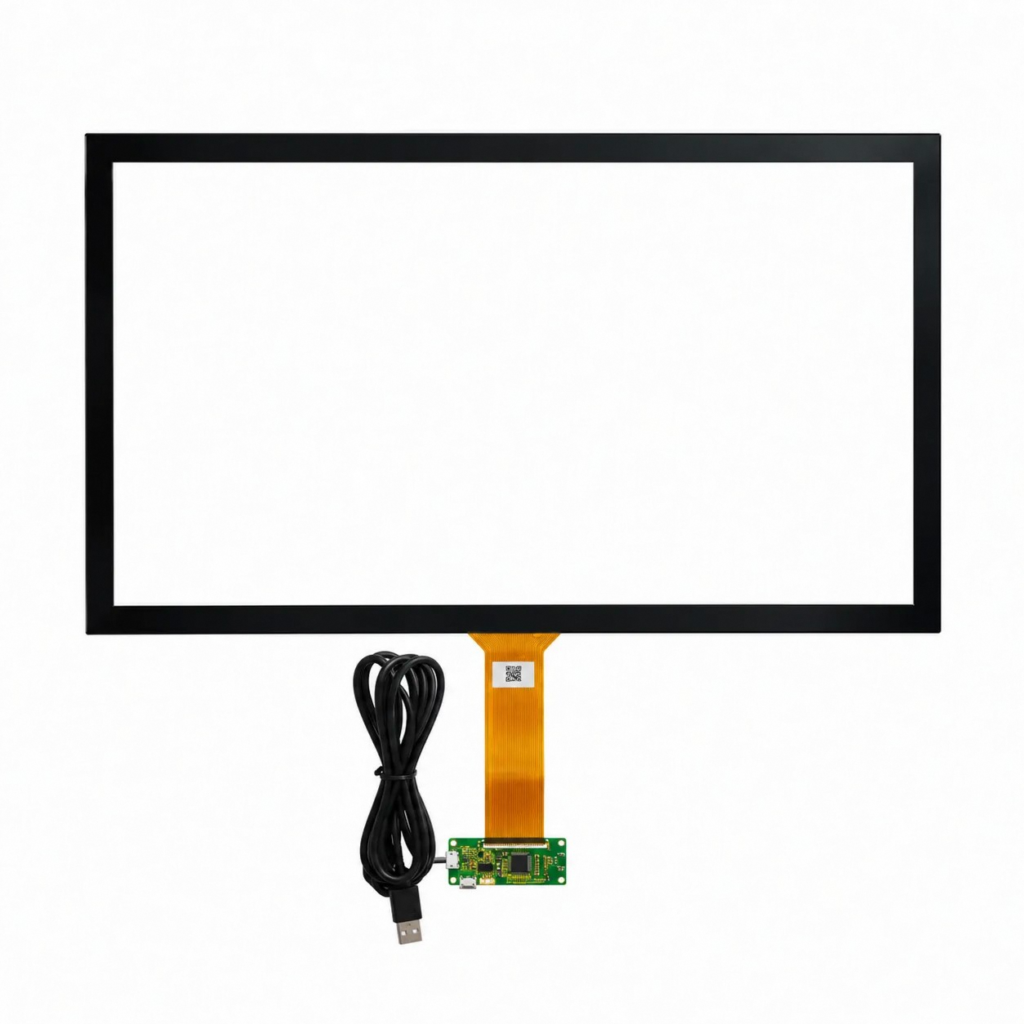
A resistive touch screen registers a deliberate press when two normally separated conductive layers make contact. The same technology is often specified as a resistive touch panel when the buyer is sourcing the complete input component.
JASPER reviews 4-wire and 5-wire constructions, active area, tail exit, connector, controller interface, display alignment and enclosure fit as one OEM stack. A finger, gloved hand or non-conductive stylus can operate the surface when the required actuation force and system calibration are designed and validated together.
Quick answer
Is a resistive touch screen the right fit?
Choose the sensing method from the real operator, interface and enclosure requirements. Pressure input is useful, but it is not the automatic answer for every display.
Good fit
Deliberate single-point pressure input
Review resistive technology when gloves, a passive stylus, legacy analog electronics or a defined press are more important than gesture control.
Review another option
Multi-touch or rigid glass-front interaction
Review capacitive technology when the UI requires pinch, zoom, light finger gestures or an unbroken rigid cover-glass surface.
Decision gate
Approve the complete stack
Wire architecture, controller, display alignment, pressure path, bezel, seal, optics and duty cycle must be validated together before release.
Operating principle
How a resistive touch panel turns pressure into coordinates
The panel is only one part of the input system. Mechanical contact creates the analog signal; the controller samples, filters and maps that signal to display coordinates.
01 / Contact
Pressure closes the spacer gap
A flexible top sheet deflects until its conductive coating touches the lower resistive layer. Spacer dots keep the layers apart when the surface is idle.
02 / Measurement
The controller reads a voltage divider
The controller applies a voltage gradient across the appropriate layer and samples the contact voltage. The wiring method determines how X and Y are driven and sensed.
03 / Mapping
Calibration converts voltage to position
Raw ADC values must be filtered and transformed for the display orientation, active-area offsets, edge behavior and the final mechanical stack.
Core product decision
4-wire and 5-wire resistive touch panel architectures
Both types use pressure to bring conductive layers together, but their electrode placement and top-film roles are different. The controller must match the chosen architecture.
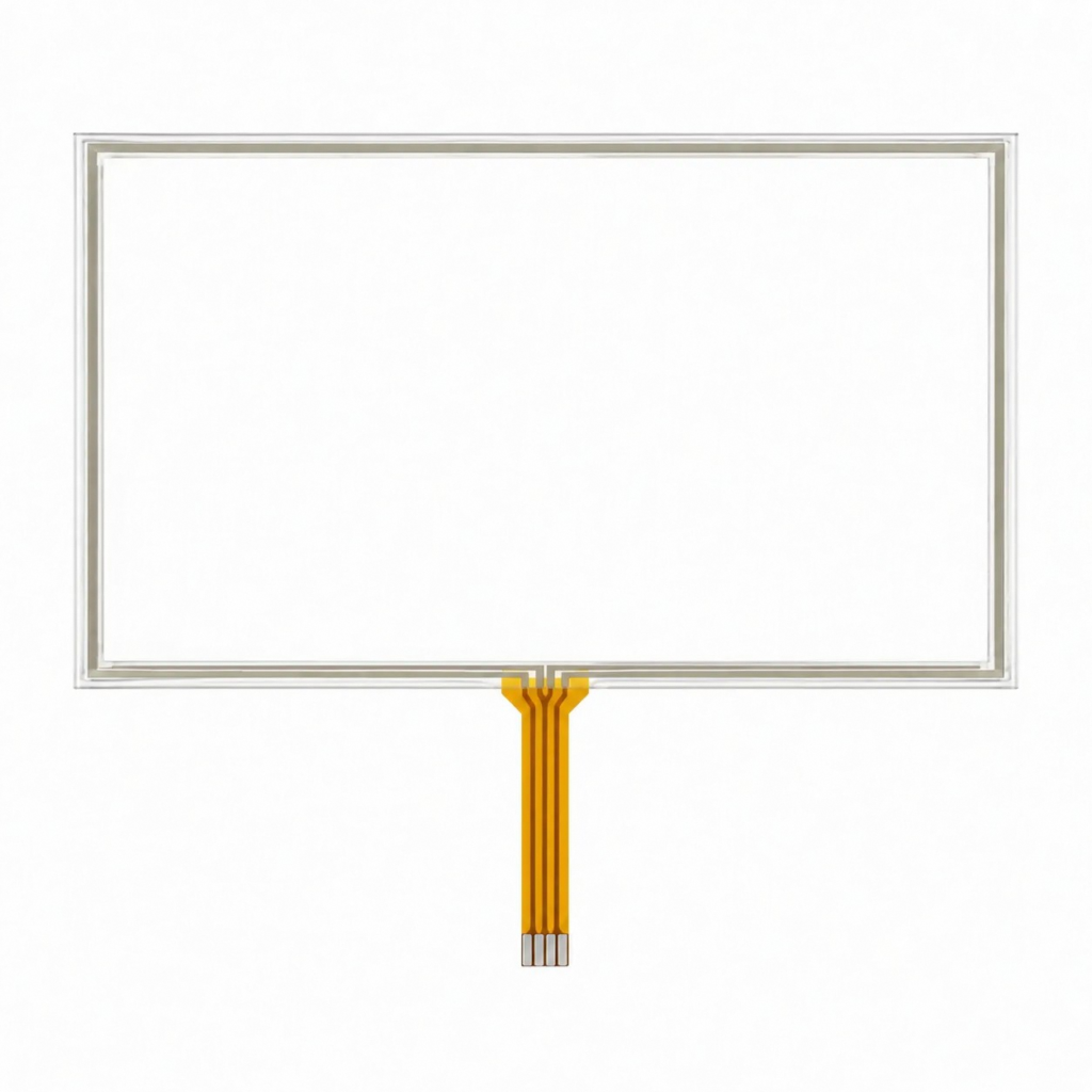
4-wire resistive touch screen
Two active resistive axes
The two conductive layers form perpendicular measurement axes. Four connections are typically identified as X+, X-, Y+ and Y-.
- The controller alternates the voltage gradient between the X and Y layers and reads the other layer for each coordinate.
- Both conductive films participate directly in coordinate measurement.
- A practical route for many cost-sensitive or replaceable industrial input assemblies when its wear profile suits the duty cycle.
- Because the top film is part of the measurement network, conductive-film wear, scratches or local damage can affect position readings.
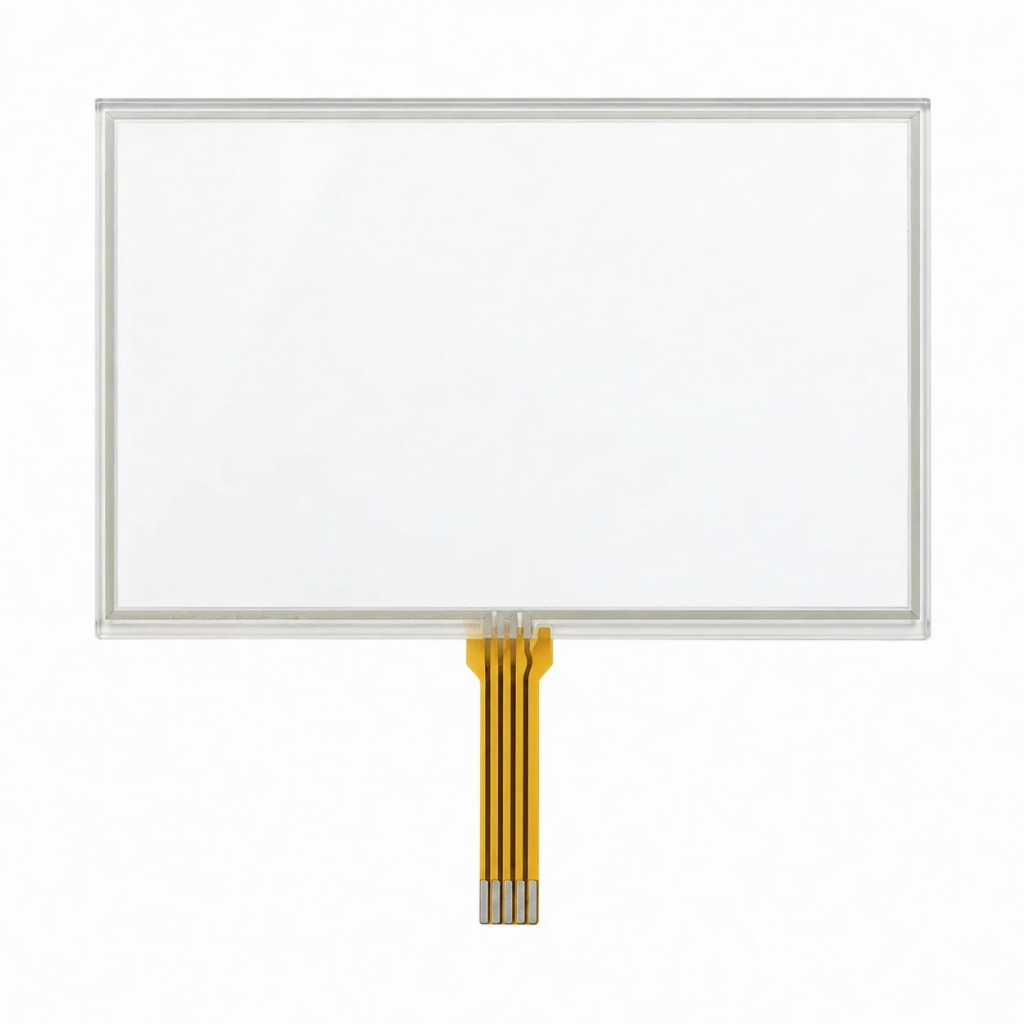
5-wire resistive touch screen and panel
Base-layer drive with one top sense lead
Four corner electrodes drive the lower resistive layer. The fifth connection is the top conductive sheet, used as the sense layer for both axes.
- The X and Y voltage gradients are created on the same base resistive layer by changing which corners are biased.
- The flexible top sheet samples contact voltage instead of carrying separate X and Y drive axes.
- This architecture is generally less sensitive to gradual uniformity loss in the top conductive coating than a 4-wire design.
- It is not immune to puncture, contamination, tail damage or controller error; the complete assembly still needs validation.
Selection table
When to specify 4-wire or 5-wire
Do not choose by wire count alone. Match the electrical architecture, duty cycle, enclosure, controller and replacement strategy.
| Decision point | 4-wire resistive | 5-wire resistive |
|---|---|---|
| Electrode arrangement | One electrode pair on each resistive layer | Four drive electrodes on the base layer plus one top sense connection |
| Top-film role | Carries one measurement axis | Senses contact voltage for both axes |
| Controller interface | Alternates drive and sense between X and Y layers | Drives base-layer corners and samples the top layer |
| Wear sensitivity | Top conductive wear can directly disturb one measurement axis | Coordinate generation remains on the base layer, reducing sensitivity to top-film uniformity changes |
| Typical selection logic | Cost, established controller platform, planned duty cycle and serviceability | Higher-use equipment where long-term top-film electrical stability is a stronger concern |
| Shared requirements | Matched controller, calibration, filtering, bezel clearance, seal and system-level testing | Matched controller, calibration, filtering, bezel clearance, seal and system-level testing |
Technology decision
Resistive touch screen vs capacitive touch panel
The better technology is the one that matches the input method, GUI, front surface and validation plan. Neither option is universally superior.
| Decision point | Resistive touch | Capacitive touch |
|---|---|---|
| Sensing method | Mechanical pressure brings two conductive layers into contact | A controller detects a change in an electric field |
| Input object | Finger, glove or passive stylus can work when the force path is validated | Finger and conductive stylus use are common; glove performance depends on the sensor, controller and glove |
| Gesture requirement | Normally selected for single-point, deliberate input | Often selected when the controller and UI require multi-touch gestures |
| Front surface | A flexible pressure path to the sensing layers is required | A rigid cover-glass construction can be designed over the sensor |
| Mechanical risks | Bezel preload, sharp tools, film wear and blocked pressure transfer | Cover thickness, grounding, display noise, moisture behavior and controller tuning |
| Typical decision | Glove or stylus input, simple controls, serviceable equipment and legacy replacement | Modern gesture UI, rigid glass appearance and light finger interaction |
Physical construction
The layer stack behind the touch surface
A resistive panel is a controlled mechanical and electrical stack. Small changes in film, spacer height, adhesive, support or bezel preload can change activation and coordinate behavior.
The diagram is generic. In 4-wire designs, both coated layers form measurement axes. In 5-wire designs, the base layer carries the drive electrodes and the top layer is the common sense sheet.
OEM integration risks
Prevent mechanical details from becoming touch faults
Many field symptoms are created by the assembled product rather than by the sensing principle. Define these interfaces on the controlled drawing and verify them in the installed stack.
Bezel
Keep continuous load away from the active area
Edge compression or gasket preload can hold the layers too close, create false contact or distort edge coordinates. Define the inactive border, support and compression range.
Pressure path
Do not block surface deflection
A decorative overlay or protective layer must transfer the intended press. Rigid or poorly supported layers can raise force, spread the touch or prevent contact.
Alignment
Register view, active and UI areas
Panel active area, display view area, enclosure opening and software targets need common datums so edge controls remain reachable after tolerance stack-up.
Tail
Route and restrain the flex connection
Tail exit, bend zone, stiffener, connector position and strain relief should prevent folding at the panel edge or loading the contact area during service.
Seal and cleaning
Treat ingress protection as a system property
The enclosure, gasket, adhesive, venting and edge design create the seal. Test the named cleaning agents, moisture exposure and assembly method; the touch panel alone does not establish an IP rating.
Optics
Review glare, air gaps and visible artifacts
Display brightness, surface finish, air gaps, adhesive and viewing angle affect reflection and image quality. Define any anti-glare or anti-Newton-ring need per project.
System boundary
Controller, calibration and noise handling are part of the design
A panel cannot guarantee usable coordinates by itself. The host electronics and firmware must be defined before the sample is approved.
Controller match
Use the correct 4-wire or 5-wire interface
Confirm drive topology, ADC inputs, voltage range, scan timing and connector pinout. A controller intended for one architecture is not automatically interchangeable with the other.
Calibration
Map the approved mechanical stack
Calibrate with the final display orientation, bezel, adhesive and mounting load. Recheck when the panel, controller, enclosure or firmware revision changes.
Filtering
Reject bounce and electrical noise
Use contact detection, settling time, repeated samples, outlier rejection and release logic appropriate to the host system and required response.
Ownership
Define who stores and controls parameters
The project should identify who owns calibration values, coordinate transforms, diagnostics, revision records and acceptance criteria.
Legacy replacement
A replacement panel cannot be selected by diagonal size alone
A drop-in claim requires mechanical, electrical and installed-system evidence. Use the old assembly as a reference, then control the replacement as a new revision.
01 / Identify
Capture the existing architecture
Record front and rear photos, labels, contact count, tail orientation, connector, controller part number and any service documentation. Do not infer the pinout from wire count alone.
02 / Measure
Rebuild the mechanical stack
Confirm outline, thickness, view area, active area, edge border, tail exit, adhesive, gasket, bezel opening and display alignment from a drawing or inspected sample.
03 / Match
Verify the electrical interface
Compare pinout, drive topology, panel resistance range where relevant, ADC/controller limits, coordinate orientation, connector engagement and firmware calibration method.
04 / Approve
Run installed first-article checks
Map the full active area and real UI targets, then verify press/release behavior, edges, tail fit, optics and calibration in the assembled equipment before production release.
Customization map
What can be reviewed for a custom resistive touch panel
The quote should describe the entire interface rather than only width and height.
Geometry
Outline and active area
Overall profile, view area, active area, edge zones, corner radii, cutouts and alignment references.
Electrical
4-wire or 5-wire circuit
Electrode architecture, tail orientation, pinout, contact pitch, stiffener and mating connector.
Surface
Optical and wear treatment
Clarity, haze, anti-glare needs, surface hardness target and cleaning exposure must be stated and verified per project.
Integration
Display and bezel fit
Viewing-area alignment, edge clearance, adhesive, gasket, mounting pressure and cable routing.
Input
Finger, glove or stylus
Name the real operator method, required activation behavior and any environmental condition that changes surface contact.
Validation
Sample and change control
Approve coordinates, edge response, optics, tail fit and the controller configuration against the controlled drawing.
Application fit
Where pressure-operated touch input can be the practical choice
Resistive technology is useful when the interface must respond to deliberate pressure instead of relying on finger capacitance. The final choice still depends on the environment and duty cycle.
Industrial
Machine and instrument controls
Gloved operation, legacy analog controllers, defined press input and replaceable front assemblies.
Medical and lab
Equipment user interfaces
Stylus or glove use can be supported, while cleaning chemistry, seal and finished-device validation remain project-specific.
Kiosk and POS
Single-touch public interfaces
Useful where single-point input, cost control and a defined service strategy matter more than multi-touch gestures.
Appliances
Embedded equipment displays
Works for deliberate on-screen selection when the bezel, tail route and controller are integrated early.
Marine and outdoor
Protected equipment interfaces
Glove input can be valuable, but pooled water, UV exposure, seal design and surface wear need explicit testing.
Special input
Passive stylus operation
A non-conductive stylus can actuate the panel when tip geometry, force and surface durability are included in validation.
Commissioning and acceptance
Separate panel, controller, firmware and mechanical causes
Troubleshooting is faster when raw behavior is recorded before parts are exchanged. Compare the unmounted panel with the final assembly and change one variable at a time.
| Observed symptom | Interfaces to investigate | First controlled checks |
|---|---|---|
| Axis is reversed or mirrored | Tail pinout, panel orientation, coordinate transform | Compare the drawing with connector mapping and log raw X/Y values before changing firmware |
| Offset or poor edge response | Calibration, active/view-area alignment, bezel preload | Calibrate in the final stack, inspect perimeter clearance and test known edge targets |
| Intermittent or dead region | Tail, connector, local layer damage, contamination | Inspect the flex and connector, map the failure area and compare with a controlled panel/controller combination |
| Noisy or false touches | ADC settling, filtering, electrical noise, moisture, continuous pressure | Log repeated raw samples, review cable routing and grounding, then remove preload or moisture as separate variables |
| Works loose but fails after assembly | Gasket load, adhesive, overlay pressure path, tail bend | A/B test unmounted and installed states while checking stack height and contact near the border |
| Units need different offsets | Calibration storage, part and mounting tolerances, revision control | Use a controlled calibration process and record panel, fixture, controller and firmware revisions |
RFQ checklist
What to send for an engineering review
A sketch is enough to start. A controlled quote needs the mechanical, electrical and use-condition inputs below.
Send Your Touch Panel Requirements- Panel outline, thickness, view area and active area
- 4-wire or 5-wire preference, if already selected
- Display model, orientation and smallest UI target
- Tail exit, length, pinout, stiffener and connector
- Controller or host ADC, drive voltage and firmware revision
- Finger, glove or stylus type and stylus-tip geometry
- Expected use frequency and field-service strategy
- Decorative overlay, protection layer and pressure path
- Bezel clearance, gasket compression, adhesive and mounting method
- Temperature, humidity, dust, moisture, UV and cleaning-agent exposure
- Optical targets, lighting and anti-glare requirements
- Old sample, photos, labels and controller details for replacement work
- Prototype quantity and forecast demand
- Acceptance criteria and owner of calibration/change control
Buyer questions
Resistive touch panel FAQ
These answers define the product boundary without inventing project-specific performance claims.
What is the difference between a resistive touch screen and a resistive touch panel?
In OEM sourcing, the terms often describe the same pressure-operated input component. Touch screen emphasizes its use over a display; touch panel emphasizes the supplied component and its mechanical, tail and controller interfaces. This page covers both keyword families on one product route.
How does a 4-wire resistive touch screen work?
It uses two coated layers arranged as perpendicular resistive axes with X+, X-, Y+ and Y- connections. The controller drives one axis, reads contact voltage on the other, then reverses the roles to obtain the second coordinate.
How does a 5-wire resistive touch panel work?
Four corner electrodes create the X and Y voltage gradients on the base resistive layer. The flexible top conductive sheet is the fifth connection and senses the contact voltage for both coordinate measurements.
Is a 5-wire panel always better than a 4-wire panel?
No. Five-wire architecture can reduce sensitivity to gradual top-film electrical wear, but project cost, controller platform, duty cycle, serviceability, optics, enclosure and validation requirements determine the better choice.
Can resistive touch panels work with gloves and a stylus?
They can respond to pressure from a finger, glove or passive stylus because the input does not depend on body capacitance. The actual glove, stylus tip, required force and surface stack must be tested with the final assembly.
Do resistive touch screens support multi-touch gestures?
Standard 4-wire and 5-wire panels are normally selected for single-point input. Specialized controllers or sensor designs may add limited gesture capability, but a project that requires native multi-touch should compare capacitive technology before the stack is fixed.
Can a rigid cover glass be placed over a resistive touch panel?
A resistive panel needs pressure to deflect the sensing layers. Any overlay or protective front must preserve that force path. A continuous rigid cover can block activation unless the complete construction is specifically engineered and validated for it.
Does a resistive touch panel need calibration?
Yes. Raw analog values must be mapped to display coordinates and filtered for stable press and release behavior. Calibration should use the approved display orientation, bezel, mounting load, controller and firmware revision.
What causes resistive touch coordinate problems?
Common sources include an unmatched controller, wrong pinout, insufficient settling or filtering, bezel preload, tail damage, layer wear, contamination, mounting changes and stale calibration parameters. Troubleshooting should separate panel, controller, firmware and mechanical causes.
Is a resistive touch panel waterproof?
The panel alone does not establish an enclosure IP rating. Edge construction, adhesive, gasket, bezel, cable exit and housing create the finished seal. Validate the assembled product against the named moisture and cleaning exposure.
Can JASPER replace an obsolete resistive touch screen?
A replacement review can begin from an old sample, photos, labels and controller information. Outline, active area, thickness, tail, connector, pinout, electrical behavior, mounting and calibration must be matched and then approved in the installed equipment.
What information is needed to quote a custom resistive touch panel?
Send the drawing or sample, view and active areas, 4-wire or 5-wire architecture, display, tail and connector, controller, input tool, overlay and bezel stack, environment, optical needs, quantities and acceptance criteria.
Start with the interface stack
Need a 4-wire or 5-wire resistive touch panel?
Send the panel drawing, active area, display information, input method, tail requirement, controller details and environment. JASPER will review the construction and integration inputs before a sample route is proposed.