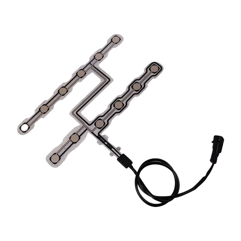
A seat occupancy sensor validation plan should prove that the correct seat state is produced across sensor samples, installed seat builds, load positions, electronics, environments, lifecycle conditions, and credible faults. Continuity or one center-load test is not enough. The plan must define the sensing architecture, fixture, reference measurement, activation and release criteria, timing, sample identity, sequence, acceptance rule, and responsibility for component, seat, controller, and vehicle-level results. Production end-of-line testing should then protect the critical characteristics established during development. The result must be reproducible.
JASPER’s custom seat occupancy sensor options can be reviewed against a project-specific drawing and test requirement. The OEM or Tier 1 team should provide the seat stack, required states, load cases, circuit, zone logic, environmental profile, lifecycle target, connector, diagnostic assumptions, sample plan, and reporting format before validation scope is frozen.
- Seat Sensor Validation at a Glance
- Define the Decision and Failure Modes Before Choosing Tests
- Freeze Test Articles, Revisions, and Responsibilities
- Golden sample and boundary samples
- Separate supplier and system ownership
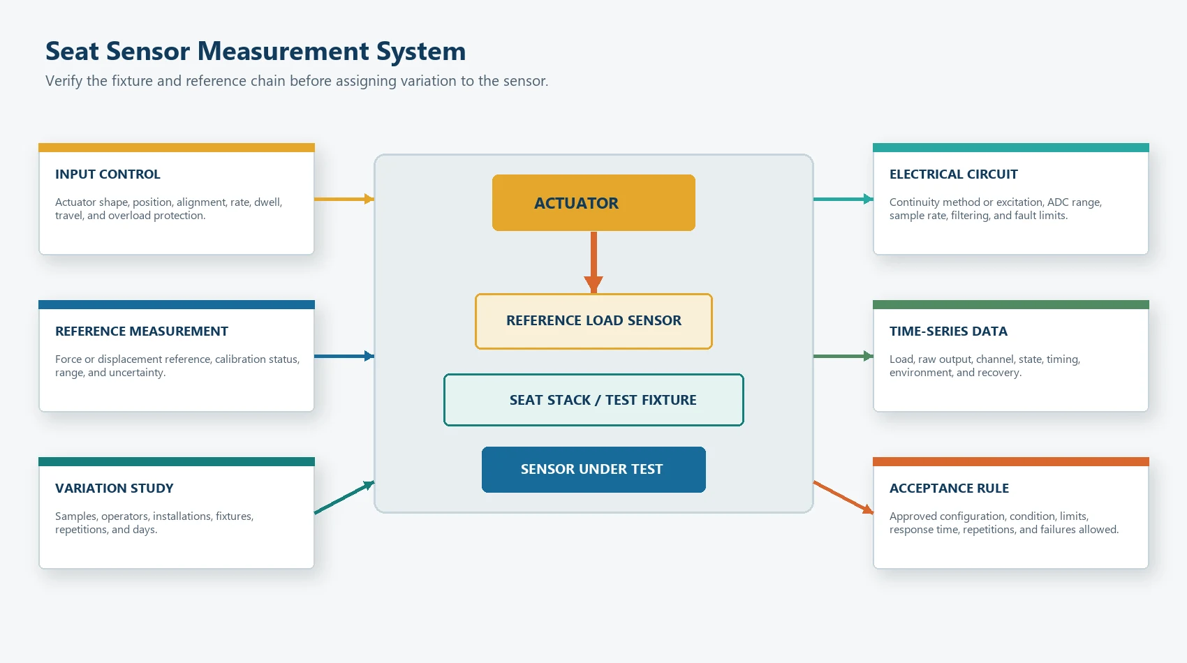
- Verify the Measurement System Before Judging the Sensor
- Reference load and actuator
- Electrical measurement
- Repeatability and reproducibility
- What Component-Level Tests Should Be Included?
- Visual inspection
- Dimensional inspection
- Continuity, open, and short tests
- Zone mapping
- How Should Activation and Release Be Tested?
- Contact-type mat
- Analog or FSR-based sensor
- Threshold and timing boundary
- Test the Installed Seat or Equipment Stack
- Required load positions
- Seat or module variation
- Loading and unloading sequence
- Environmental Conditioning
- Condition, measure, recover, remeasure
- Standards are inputs, not automatic pass marks
- Mechanical Durability and Lifecycle Tests
- Repeated loading
- Dwell, recovery, and compression effects
- Concentrated and off-axis load
- Tail and connector durability
- Vibration and shock
- Fault Injection and Diagnostic Validation
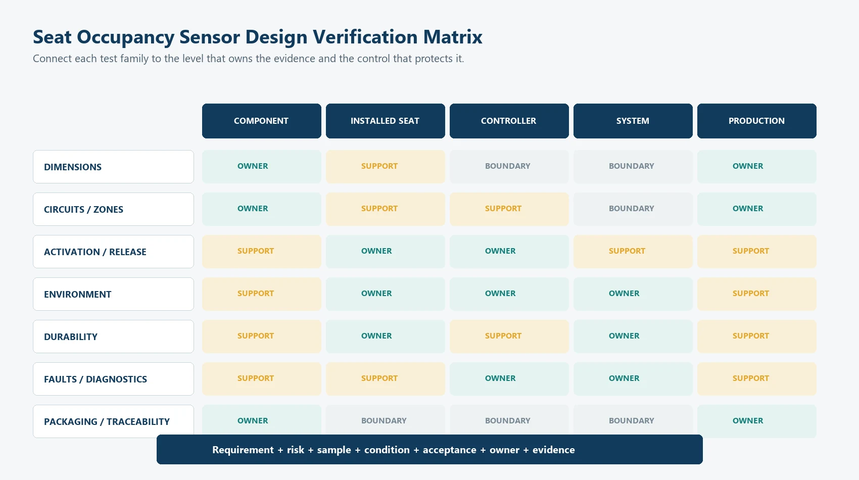
- Build a Design Verification Matrix
- How Many Samples and Repetitions Are Needed?
- Write Acceptance Criteria Before Running the Test
- End-of-Line Testing and Production Control
- Good candidates for end-of-line or in-process checks
- Tests that may remain periodic, qualification, or change-based
- Test Reports and Data Traceability
- Change Control and Revalidation Triggers
- Automotive and System-Level Boundary
- Common Seat Sensor Testing Mistakes
- Testing only one bare sensor
- Calling continuity a functional test
- Using an unverified fixture
- Recording only pass/fail
- Measuring only activation
- Applying a standard without defining severity
- Reusing a threshold after a mechanical change
- Running the full development matrix on every production unit
- Claiming vehicle compliance from component data
- OEM Input Checklist for a Validation Plan
- Build the Validation Matrix Before Samples Are Approved
- Sources
Seat Sensor Validation at a Glance
| Validation layer | Main question | Typical evidence | Primary owner |
|---|---|---|---|
| Sensor component | Was the sensor built and wired according to the approved drawing? | Dimensions, appearance, continuity, short/open, zone map, contact or analog output | Sensor supplier with customer-approved criteria |
| Installed seat or module | Does the real load path produce repeatable activation and release? | Seat fixture data, load positions, preload, dwell, edge cases, assembly variation | Seat integrator and sensor supplier |
| Controller interface | Does the electronics chain interpret valid, transitional, and fault inputs correctly? | Circuit data, ADC or logic states, thresholds, timing, diagnostics, fault injection | Electronics and system team |
| Complete system | Does the intended reminder, comfort, monitoring, or control function behave correctly? | System state tests, user/load cases, fault reactions, environmental and lifecycle evidence | OEM or system owner |
| Vehicle or regulated product | Does the final product meet applicable program and regulatory requirements? | Program-specific compliance and approval records | OEM or legally responsible manufacturer |
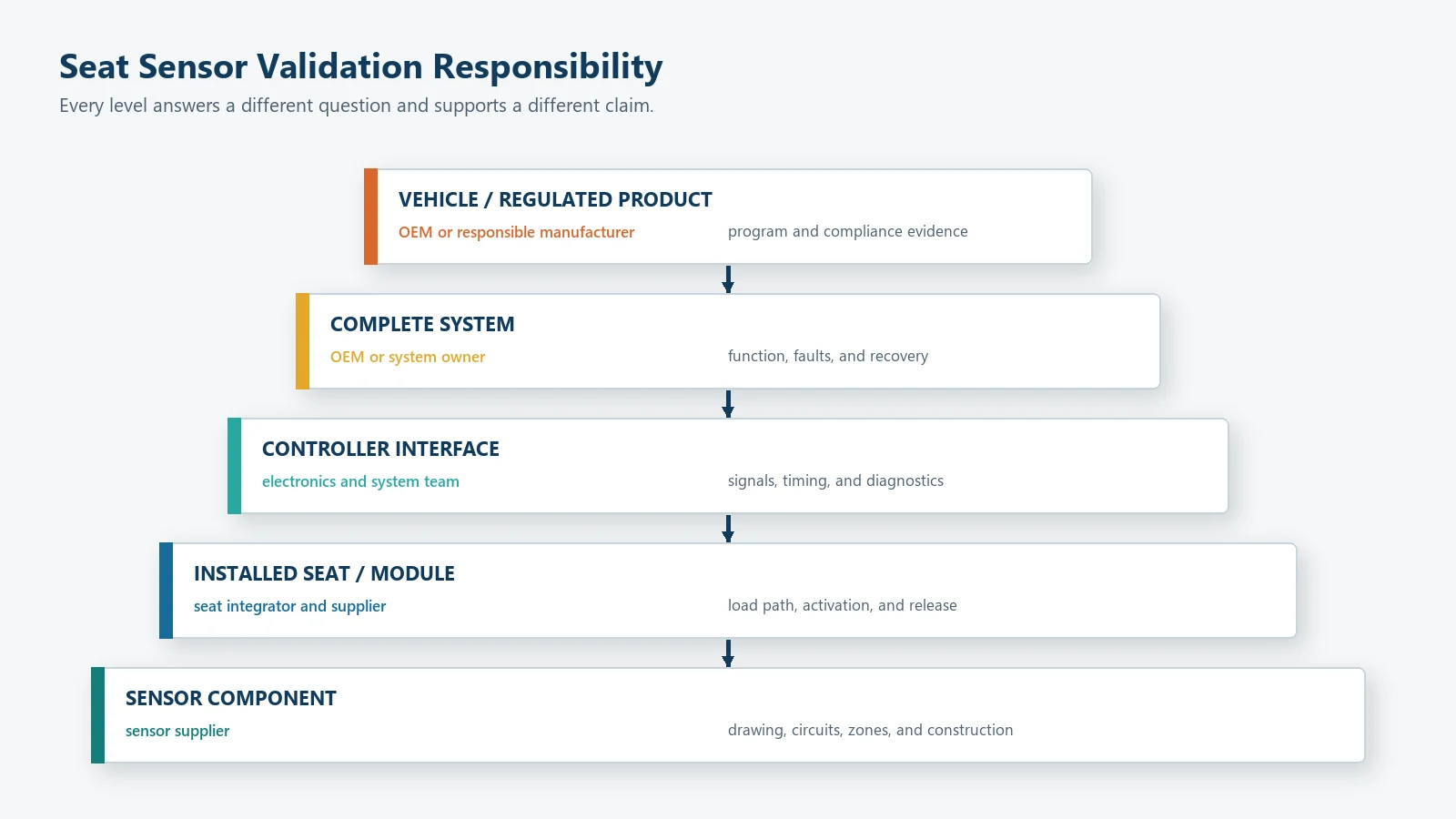
The same test name can mean different things at each layer. Cycle test, for example, might mean repeatedly pressing a bare sensing zone, loading the complete cushion, moving a seat mechanism, or running the full system state machine. The test plan must identify the level.
The companion guide on how seat occupancy sensors work maps the complete path from applied load through the seat stack, sensor, electronics, decision logic, and final system state.
Define the Decision and Failure Modes Before Choosing Tests
Testing starts with a requirement, not a laboratory menu.
Define:
- required empty state;
- required occupied state;
- transitional or ambiguous conditions;
- startup and unknown state;
- electrical fault state;
- activation and release behavior;
- allowed response time;
- required sensing zones or zone combinations;
- conditions that must not activate the system; and
- the action owned by the final controller.
Then list the ways the decision could be wrong.
| Failure mode | Example cause | Test needed to expose it |
|---|---|---|
| False occupied | Foam or trim preload, local rib, stuck contact, signal drift | Empty-seat builds, preload, dwell, environment, fault checks |
| Missed occupied | Zone outside the load path, insufficient force transfer, open circuit | Required load positions, zone edges, continuity, seat variation |
| Chatter | Contact bounce, movement, noisy analog boundary, loose connector | Transition logging, hysteresis/debounce review, connector disturbance |
| Slow activation | Load spreading, filtering, mechanical travel, timing rule | Time-stamped loading and controller-state test |
| Slow or failed release | Foam recovery, adhesion, contact sticking, analog drift | Unloading, dwell, recovery, repeated-cycle test |
| Wrong zone | Trace or pin mapping error, printing or assembly shift | Zone-by-zone activation and pinout verification |
| Intermittent signal | Tail damage, connector movement, cracked trace | Harness handling, bend, vibration where applicable, continuity logging |
| Fault treated as normal state | Missing diagnostic or undefined system reaction | Open/short/out-of-range fault injection |
Do not add a test because it sounds rigorous. Add it because it protects a requirement or detects a credible failure.
Freeze Test Articles, Revisions, and Responsibilities
A validation result is only useful when the tested configuration is traceable.
Record for every sample:
- sensor part number and revision;
- sensor lot or build date;
- seat, cushion, foam, trim, support, and module revisions;
- installation position and orientation;
- adhesive or mounting method;
- tail route and connector;
- controller hardware and software revision;
- measurement circuit and settings;
- fixture revision;
- calibration status of reference equipment;
- test operator;
- date and environmental condition; and
- any deviation or rework.
Golden sample and boundary samples
An approved reference sample can help compare feel, fit, or signal behavior, but it should not replace numerical or state-based criteria. Include samples that represent relevant design and process boundaries rather than selecting only the best-looking units.
Separate supplier and system ownership
The supplier can confirm a component against an approved drawing and agreed test. The seat integrator can confirm installation and load transfer. The electronics team can confirm interface and diagnostics. The OEM or system owner confirms the final functional and regulatory outcome.
One report should not silently absorb all four responsibilities.
Verify the Measurement System Before Judging the Sensor
If the fixture or measurement method is unstable, the result cannot distinguish sensor variation from test variation.
Reference load and actuator
Document:
- reference force or load measurement method;
- actuator shape and contact area;
- alignment;
- loading direction;
- loading and unloading rate;
- support surface;
- travel or compression control;
- dwell;
- data-sampling rate; and
- overload protection.
The fixture should reproduce the intended load path or state clearly that it is a component-screening fixture, not a seat-system simulation.
Electrical measurement
For a contact sensor, define:
- open and closed criteria;
- measurement current or continuity method;
- contact stability;
- bounce capture;
- open/short limits; and
- zone-to-pin mapping.
For an analog sensor, define:
- excitation or divider circuit;
- reference voltage;
- meter or ADC range;
- sample rate;
- filtering;
- signal direction;
- baseline;
- load or signal bands;
- fault limits; and
- data conversion.
Repeatability and reproducibility
Run repeated measurements on the same sample without changing the intended condition. Then vary operators, fixtures, installations, or days where those sources matter.
Measurement-system studies separate repeatability from reproducibility and use measurement evidence to determine whether observed variation belongs to the gauge or the part. Measurement systems analysis provides a framework for this assessment in automotive projects. The project should select a method appropriate to the output, data type, risk, and customer process.
Do not report a gauge result without identifying:
- study design;
- samples;
- operators;
- repetitions;
- range of the characteristic;
- calculation method; and
- acceptance rule.
What Component-Level Tests Should Be Included?
Component tests confirm the sensor assembly before the surrounding seat or equipment adds variation.
Visual inspection
Check agreed criteria for:
- cut edges and internal cutouts;
- layer alignment;
- contamination;
- wrinkles, bubbles, or delamination;
- trace or print defects visible through the construction;
- tail and stiffener condition;
- connector orientation;
- label, revision, and traceability;
- protective liner; and
- packaging damage.
Appearance criteria should separate cosmetic conditions from defects that affect fit, electrical function, sealing, or durability.
Dimensional inspection
Measure critical features such as:
- overall outline;
- active-zone position;
- holes and cutouts;
- tail exit;
- tail length;
- connector position;
- critical layer registration;
- adhesive outline; and
- mounting datums.
Do not give every dimension the same inspection priority. Focus on characteristics that protect the load path, electrical routing, connector fit, or assembly.
Continuity, open, and short tests
Verify:
- intended connections are present;
- unintended connections are absent;
- common returns and zone lines match the drawing;
- pin numbering and connector orientation are correct;
- tail and connector handling do not create intermittency; and
- the test can distinguish a valid sensor state from a wiring fault.
A continuity result proves only the tested circuit condition. It does not prove activation force, seat coverage, analog calibration, or lifecycle.
Zone mapping
Activate one zone at a time and record:
- expected pin or channel;
- neighboring-zone response;
- shared-return behavior;
- inactive-zone condition;
- crosstalk or unintended activation; and
- zone label versus drawing.
Zone mapping is especially important when the mat and connector can be installed in more than one orientation.
How Should Activation and Release Be Tested?
Activation and release are separate events. Test both loading directions.
Contact-type mat
Record:
- load or displacement at first valid closure;
- stable closed condition;
- release condition;
- bounce;
- repeated closure;
- preload sensitivity;
- edge and off-center behavior; and
- state after dwell.
The final acceptance may be defined in load, displacement, fixture position, state, or another customer-approved quantity. Do not invent a universal trigger weight.
Analog or FSR-based sensor
Record:
- baseline;
- signal during controlled loading;
- signal during unloading;
- repeatability;
- hysteresis;
- drift during dwell;
- recovery;
- sensitivity to contact area and position;
- circuit and ADC behavior; and
- fault limits.
Analog testing should distinguish the raw sensor response from the controller’s final occupancy decision.
Threshold and timing boundary
This article does not assign a universal T_on, T_off, hysteresis width, filter, or debounce time. Those values must come from the project data and system requirement.
Use the testing plan to collect the empty, transitional, and occupied distributions needed for a separate threshold decision. If those distributions overlap, more filtering does not create missing physical separation.
The separate pressure sensor mat calibration guide explains how to evaluate thresholds, hysteresis, debounce, and guard bands after the physical test method and data distributions are defined.
Test the Installed Seat or Equipment Stack
The bare sensor does not represent foam, trim, support, upholstery tension, product covers, adhesives, or assembly preload.
Use the pressure sensor mat design guide to freeze active zones, load paths, stack construction, mounting, tail routing, connector details, and prototype evidence before installed-seat validation begins.
Required load positions
Include:
- center of each required sensing zone;
- edges of each zone;
- gaps between zones;
- relevant front/rear and left/right positions;
- expected posture or product-position extremes;
- required non-sensing locations;
- areas near ribs, cutouts, seams, or supports; and
- transitional movement between positions.
Seat or module variation
Use representative variation in:
- foam or cushion builds;
- trim tension;
- support structure;
- sensor placement;
- mounting adhesive;
- seat adjustment;
- product tolerances;
- repeated assembly; and
- connector and tail routing.
The objective is not to create random variation. It is to include the credible boundaries that can move the system decision.
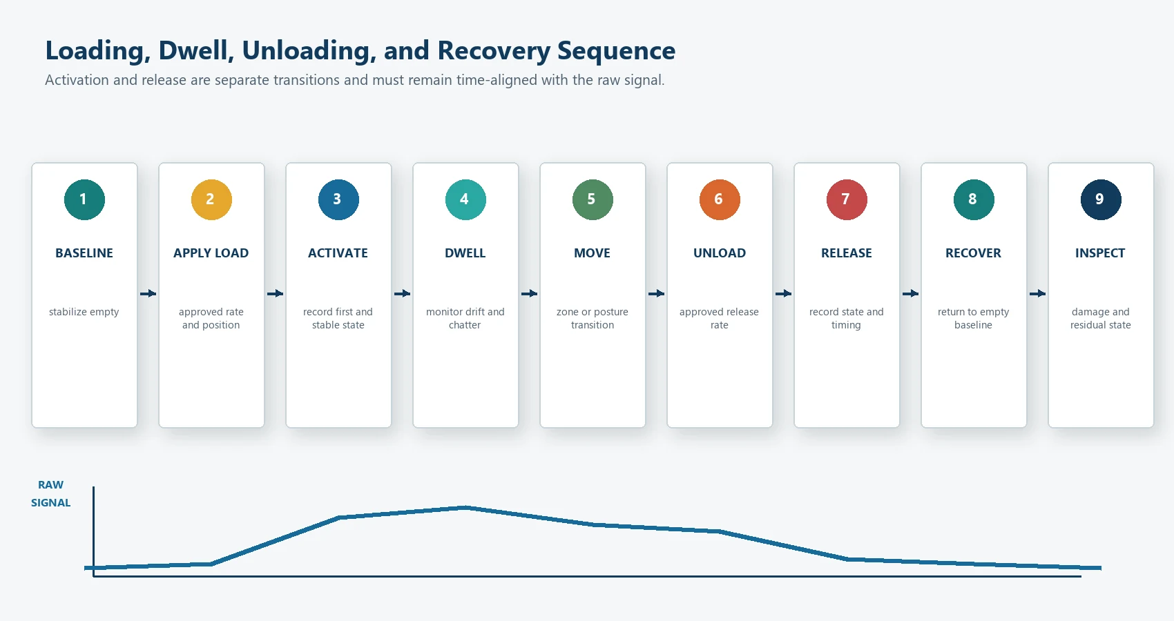
Loading and unloading sequence
Define:
- initial empty stabilization;
- load application;
- activation observation;
- dwell;
- movement or zone transition if required;
- unloading;
- release observation;
- recovery;
- final empty observation; and
- inspection for damage or residual state.
The same sequence should be used across samples unless the test intentionally studies sequence effects.
Environmental Conditioning
Environmental tests should represent the product location, material stack, use conditions, storage, transport, and customer specification.
Possible factors include:
- high and low temperature;
- temperature change;
- humidity;
- moisture or condensation risk;
- cleaning or chemical exposure;
- storage;
- thermal dwell;
- powered or unpowered condition;
- recovery after conditioning; and
- combined environment and mechanical load.
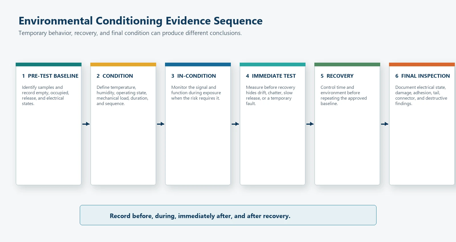
Condition, measure, recover, remeasure
For each environment, define whether the sensor is:
- measured before conditioning;
- operating during conditioning;
- mechanically loaded during conditioning;
- measured immediately after exposure;
- allowed to recover;
- measured after recovery; and
- inspected destructively at the end.
A single post-test continuity check can miss temporary drift, delayed recovery, chatter, or a fault that occurs only during exposure.
Standards are inputs, not automatic pass marks
IEC 60068-1 provides general principles and guidance for environmental testing, while individual IEC 60068-2 methods address specific stresses. IEC 60068-2-78, for example, covers damp heat, steady state.
ISO 16750 addresses environmental conditions and testing for electrical and electronic equipment in road vehicles. Parts 3 and 4 cover mechanical and climatic loads. Applicability, severity, mounting location, operating mode, sequence, and acceptance still require the OEM program to define them.
Do not write tested to IEC 60068 or meets ISO 16750 unless the exact part, method, edition, severity, configuration, sample plan, and acceptance result are documented.
Mechanical Durability and Lifecycle Tests
Repeated loading
Define:
- load shape and area;
- peak and minimum condition;
- loading rate;
- cycle frequency;
- dwell;
- seat or product stack;
- powered or unpowered electronics;
- inspection intervals;
- measurement intervals; and
- failure criteria.
Cycle count alone is not a complete test specification.
Dwell, recovery, and compression effects
A sustained load can change foam, adhesive, contact spacing, force-sensitive material, or the support stack. Measure:
- output at the start of dwell;
- output during dwell;
- release behavior;
- time to return to the approved empty condition; and
- response after repeated dwell cycles.
If the assembly includes foam or another compliant layer, distinguish sensor behavior from cushion compression or recovery.
Concentrated and off-axis load
Use concentrated, edge, angled, or off-axis cases only when they represent credible use, assembly, or abuse. Record whether the objective is functional performance, survival, or damage characterization.
Tail and connector durability
Check:
- tail bend location;
- one-time or repeated flex duty;
- strain relief;
- connector retention;
- pin stability;
- rubbing or sharp edges;
- harness movement;
- continuity during movement where required; and
- condition after seat or product assembly.
Do not use the tail as a lifting or fixture attachment point unless the design specifically allows it.
Vibration and shock
Vibration or shock may belong at the component, seat module, equipment, or vehicle level. Use the mounting configuration, axes, operating state, duration, and monitoring required by the project. A loose sensor in a chamber does not represent an installed seat.
Fault Injection and Diagnostic Validation
The controller should distinguish a valid empty or occupied condition from relevant faults.
Candidate faults include:
- open sensor line;
- short between lines;
- short to supply or ground where applicable;
- disconnected connector;
- reversed or wrong connector;
- stuck contact;
- analog signal outside the valid range;
- one failed zone;
- inconsistent zone combination;
- intermittent tail or harness; and
- unknown startup state.
For each fault, document:
- injection point;
- electrical condition;
- expected diagnostic;
- expected system state;
- response time;
- recovery behavior;
- stored fault behavior if applicable; and
- responsibility for the final action.
Fault injection should not damage the controller or bypass a safety function. Use approved methods and protected test equipment.
Build a Design Verification Matrix
The matrix should connect requirements, risks, tests, samples, conditions, and results.
| Test family | Example characteristic | Development qualification | Production control |
|---|---|---|---|
| Appearance and construction | Cut, layers, contamination, label, connector | Review all design risks and defect standards | Visual criteria at agreed frequency |
| Dimensions | Outline, zones, tail, datums, cutouts | Full dimensional study across representative builds | Critical dimensions by agreed sampling or control plan |
| Electrical integrity | Continuity, short/open, pinout, zone map | All functions plus fault and handling cases | End-of-line circuit checks where feasible |
| Activation/release | Contact state or analog response | Loads, positions, directions, dwell, variation | Project-specific functional screen or sampling |
| Installed assembly | Foam, trim, support, sensor position | Multiple representative seat/module builds | Assembly controls and audits |
| Environment | Temperature, humidity, recovery, combined stress | Approved design-validation matrix | Material/process controls; periodic or change-based tests |
| Durability | Cycles, dwell, tail, connector, wear | Qualification and failure analysis | Process controls; periodic verification if required |
| Diagnostics | Open, short, zone disagreement, startup | Controller and system validation | End-of-line fault checks if supported |
| Packaging and transport | Tail, connector, liner, traceability | Packaging qualification | Shipment inspection |
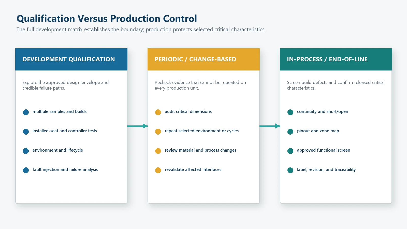
Development qualification and production testing are not the same. Qualification explores the design envelope. Production control screens defects and monitors the approved process.
How Many Samples and Repetitions Are Needed?
There is no universal sample count for every seat sensor.
The plan should consider:
- number of sensor lots or builds;
- number of seat, cushion, or equipment builds;
- production tools or cavities;
- zones and channels;
- operators and fixtures;
- destructive versus non-destructive tests;
- environmental chambers;
- expected variation;
- failure consequence;
- customer approval process; and
- statistical objective.
Possible objectives include:
- demonstrate functional feasibility;
- estimate repeatability;
- compare revisions;
- characterize distribution;
- verify a design boundary;
- qualify a process;
- screen production defects; or
- detect a specified failure rate with stated confidence.
Do not select a sample count first and invent the statistical purpose later.
Write Acceptance Criteria Before Running the Test
A useful criterion identifies the configuration, input, expected result, timing, repetitions, and allowed failures.
Given:
    approved sensor, seat or module, controller, and fixture revisions
    defined preconditioning and environmental state
    defined empty, occupied, transitional, or fault input

When:
    the input is applied using the approved location, actuator, rate, and dwell

Then:
    the measured signal and system state shall meet the approved limits
    within the approved response time
    without prohibited chatter, intermittency, damage, or diagnostic error

Record:
    raw data, state transitions, sample identity, fixture, operator,
    environment, deviations, and final result

Repeat:
    across the specified samples, positions, cycles, and conditions
Avoid criteria such as:
works normally;no obvious problem;similar to sample;passes cycle test; orsensor activates at approximately the target.
Those phrases do not define a reproducible decision.
End-of-Line Testing and Production Control
The approved development data should identify characteristics that can be controlled during production.
Good candidates for end-of-line or in-process checks
Depending on architecture and feasibility:
- continuity;
- short/open;
- pinout;
- zone mapping;
- connector orientation;
- simple contact activation;
- analog range at an approved fixture condition;
- label and revision;
- critical dimensions;
- appearance;
- tail and connector condition; and
- traceability.
Tests that may remain periodic, qualification, or change-based
- full environmental sequences;
- long lifecycle cycling;
- destructive analysis;
- multiple seat-build studies;
- complete controller fault injection;
- vehicle-level function; and
- regulatory validation.
JASPER’s testing and quality-control framework describes drawing-based visual, dimensional, electrical, actuation, bonding, connector, and packaging inspection for custom interface assemblies. Seat-sensor checks must be confirmed for the actual product and order; the page should not be read as proof that every sensor receives every test in this article.
Test Reports and Data Traceability
A validation report should include:
- requirement and test ID;
- sensor, seat/module, controller, fixture, and software revisions;
- sample and lot identity;
- equipment and calibration record;
- method and sequence;
- raw data location;
- processed result and calculation;
- acceptance criterion;
- pass/fail result;
- photos or diagrams;
- anomalies and deviations;
- failure analysis;
- corrective action;
- retest scope;
- approval signatures or roles; and
- change-control impact.
Keep raw data. A summary table without time history, load trace, channel identity, or environmental condition may be impossible to audit after a failure.
Change Control and Revalidation Triggers
Revalidation may be required when changing:
- sensor outline or active zones;
- conductor, spacer, sensing, adhesive, or protective material;
- layer thickness or lamination process;
- printing, cutting, tooling, or registration method;
- tail length, exit, stiffener, connector, or terminal;
- supplier or material source;
- seat foam, trim, support, or sensor position;
- measurement circuit, firmware, thresholds, filter, or timing;
- assembly fixture or process;
- environmental or lifecycle requirement;
- inspection method; or
- packaging that protects the tail or sensor body.
Classify each change by affected requirement and decide whether it needs document review, limited verification, partial requalification, or full revalidation.
Automotive and System-Level Boundary
For automotive applications, a component pass does not prove that the complete vehicle function passes.
The program may need to evaluate:
- seat and cushion variants;
- seat position;
- buckle input;
- controller and network behavior;
- warning timing;
- occupant or object cases;
- diagnostics;
- startup and power conditions;
- restraint-system interactions;
- vehicle environment; and
- applicable regulatory requirements.
49 CFR 571.208 defines occupant-protection requirements at the vehicle level. This article does not provide a compliance procedure, universal vehicle threshold, warning setting, or occupant-classification rule.
Common Seat Sensor Testing Mistakes
Testing only one bare sensor
One component cannot represent sensor, seat, assembly, electronics, environment, and lot variation.
Calling continuity a functional test
Continuity can confirm an electrical path. It does not prove the load path, activation, release, timing, coverage, or diagnostics.
Using an unverified fixture
Fixture misalignment, friction, actuator wear, support compliance, or reference-gauge variation can look like sensor variation.
Recording only pass/fail
Raw load, signal, time, channel, environment, sample, and fixture data are needed to understand margin and drift.
Measuring only activation
Release, recovery, dwell, movement, chatter, and fault handling are separate risks.
Applying a standard without defining severity
A standard family name is not a test condition. Record the exact method, edition, severity, mounting, operating mode, sequence, samples, and acceptance.
Reusing a threshold after a mechanical change
Foam, trim, adhesive, support, sensor position, or zone changes can move the signal distributions.
Running the full development matrix on every production unit
This is usually impractical and may damage the product. Build production controls around the critical characteristics proven during qualification.
Claiming vehicle compliance from component data
The final system and responsible manufacturer own vehicle-level validation.
OEM Input Checklist for a Validation Plan
Provide:
- Product function and seat or equipment position.
- Required empty, occupied, transitional, unknown, and fault states.
- Sensor architecture, output, zones, drawing, tail, connector, and pinout.
- Seat, cushion, trim, support, adhesive, and installation stack.
- Load cases, positions, contact areas, rates, dwell, and unloading sequence.
- Circuit, supply, ADC or digital input, sample rate, filters, thresholds, and timing.
- Fault conditions and expected diagnostic/system response.
- Temperature, humidity, storage, transport, cleaning, vibration, shock, and other
relevant environments. - Lifecycle, repeated loading, dwell, recovery, tail, and connector requirements.
- Applicable customer, IEC, ISO, regulatory, or internal specifications.
- Sample quantities, lots, seat builds, fixtures, operators, and repetitions.
- Acceptance criteria, data format, report template, and approval roles.
- Production end-of-line, sampling, traceability, and change-control expectations.
If the customer has not selected the conditions, provide the real use environment and risk analysis first. The test matrix should follow the application, not a copied list.
Frequently Asked Questions
What is the difference between verification and validation?
Verification checks whether the sensor or design meets specified requirements. Validation checks whether the installed product and system perform the intended function in the real or representative application. OEM programs often need both.
Is continuity testing enough for a seat occupancy sensor?
No. Continuity can find an open path, short, or pinout error. It does not prove activation, release, seat coverage, timing, preload behavior, analog response, environmental stability, durability, or system diagnostics.
Should the sensor be tested inside the real seat?
Yes, when the final function depends on foam, trim, support, sensor position, or assembly preload. Component fixtures remain useful for inspection and comparison, but they do not replace installed-seat validation.
How many cycles should a seat sensor pass?
There is no universal cycle count. Define the use profile, load, rate, dwell, environment, inspection intervals, failure criteria, and required design margin for the project.
How many samples are needed?
Sample size depends on the statistical objective, expected variation, number of lots and seat builds, destructive tests, failure consequence, and customer approval process. State the purpose before choosing the count.
Does JASPER perform every test listed here?
No blanket claim is made. JASPER can review project-specific component inspection and test requirements. The confirmed scope depends on the sensor construction, drawing, equipment, sample stage, order, and customer agreement. Seat, controller, system, vehicle, and regulatory validation remain with the responsible project parties.
Can an IEC or ISO standard be used as the complete test plan?
Not by name alone. The project must identify the exact standard part and edition, severity, mounting, operating mode, sequence, sample plan, monitoring, recovery, and acceptance criteria. Additional application-specific tests may still be required.
Build the Validation Matrix Before Samples Are Approved
Send the sensor drawing, seat stack, required states, load cases, circuit, zones, environments, lifecycle target, connector, fault strategy, sample plan, and acceptance criteria through the JASPER RFQ form. The first review should separate component inspection, installed-seat validation, controller testing, and final system responsibility.
Sources
- JASPER Electronics, “Custom Car Seat Occupancy Sensor and Seat Pressure Mat Manufacturer.” https://www.jasperele.com/products/car-seat-occupancy-sensor/
- JASPER Electronics, “Membrane Switch Testing and Quality Control.” https://www.jasperele.com/quality/testing/
Ready to Start Your Project?
Tell us about your membrane switch, keypad, or graphic overlay requirements. Our engineering team will review your specifications and provide a detailed quote.