
PRODUCT KNOWLEDGE
What Is a Seat Occupancy Sensor?
A seat occupancy sensor provides information that a control system uses to determine whether a seat is occupied. It may respond to pressure, structural load, or an electrical-field change. A flexible pressure mat is one implementation—not a complete occupant classification or airbag control system. Its usefulness depends on the seat construction, electronics, decision logic, and validation around it.
Read the guide ↓
In this guide
- What does a seat occupancy sensor actually detect?
- What is inside a flexible seat sensor mat?
- How does the signal become an occupancy decision?
- Pressure mats, load sensors, and capacitive sensing
- How the seat sensor product routes fit together
- Why the seat construction changes the result
- Outputs, calibration, and the limits of a threshold
- Where seat occupancy information is used
- What should an engineering validation plan cover?
- Seat occupancy sensing is not the whole safety system
- What to include in a seat sensor specification
- Frequently asked questions
What does a seat occupancy sensor actually detect?
Seat occupancy describes the information required by an application; it does not specify one sensing technology. A sensor measures a physical effect. The controller interprets that measurement and produces a state such as occupied, unoccupied, or fault. Keeping those responsibilities separate prevents a simple sensing element from being specified as though it were a finished vehicle safety system.
In a pressure-based design, the cushion transfers part of an applied load to one or more active regions. The sensor responds to that local loading, not necessarily to the occupant’s total body weight. Feet, backrest support, posture, cushion shape, and objects placed on the seat can change the response. A pressure signal alone does not establish a person’s identity, age, or safe airbag strategy.
The car seat occupancy sensor product family covers thin sensing components and seat-pressure structures for integration into a larger assembly. When comparing options, first decide whether the project needs basic presence information, a changing load signal, or a validated occupant classification function. These are different requirements even when their parts fit into similar spaces.
What is inside a flexible seat sensor mat?
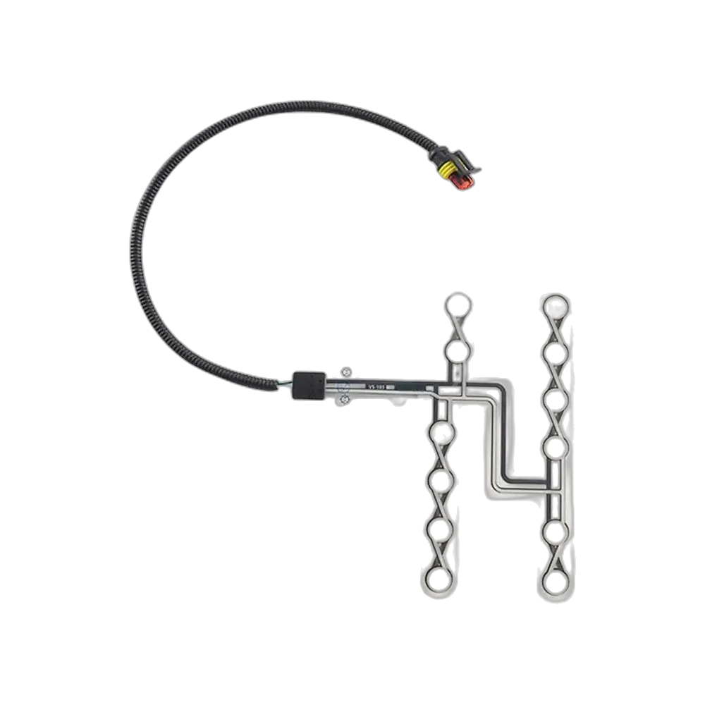
A flexible mat can combine polymer films, printed conductors, sensing regions, insulating layers, and a tail or cable connection. Polyester, also called PET, is one possible film substrate. The actual stack depends on the sensing principle and manufacturing design; not every mat contains the same number of layers or the same resistive material.
| Part of the assembly | Main job | Important design question |
|---|---|---|
| Film carrier | Holds the printed pattern and allows a thin profile | How will it bend and be supported inside the seat? |
| Conductive traces | Carry signals between active regions and the connection | Are traces protected from repeated creasing and abrasion? |
| Active sensing region | Converts local loading into an electrical change | What contact area and load path will reach it? |
| Spacer or dielectric layer | Separates or insulates parts where the design requires it | Can compression, contamination, or tolerances change its behavior? |
| Laminated cover and attachment features | Protect and position the assembly | Do attachment points add unwanted preload? |
| Tail, cable, and connector | Connect the mat to the receiving circuit | What prevents strain, pinching, or incorrect connection? |
A contact-style mat may close a circuit when its layers meet. A force-sensitive resistive construction instead changes resistance as loading changes. Either can use multiple active regions, but multiple printed circles do not automatically mean independently measured channels. The drawing and circuit definition must say whether regions are connected together or read separately.
A laminated edge is not proof of waterproofing, and a flexible outline is not permission to fold the part anywhere. The finished seat assembly needs its own environmental and mechanical assessment.
How does the signal become an occupancy decision?
The chain begins with mechanics and ends with an application decision. Loading changes the sensor’s electrical condition; an input circuit reads it; software or dedicated logic evaluates the reading; the vehicle or equipment controller uses the resulting state. A passive pressure mat normally does not perform all of these steps itself.
For a contact sensor, the input circuit recognizes an electrical state associated with actuation. For a resistive sensor, the circuit measures a resistance-dependent voltage or current. It may then convert the measurement into digital data. The direction and range of the reported voltage depend on the circuit, so a lower sensor resistance does not universally mean a higher output voltage.
Decision logic may include thresholds, persistence time, and a separate release condition. These can reduce unwanted switching when someone shifts position. More filtering also adds delay. The acceptable trade-off comes from the function being served, not from the mat’s outline or a generic settings table.
Fault handling belongs in the same discussion. An open wire, short circuit, or implausible signal must not automatically be treated as an empty seat. Whether the system can distinguish those conditions depends on its diagnostic design. A connector that physically fits is insufficient evidence of electrical or functional compatibility.
Pressure mats, load sensors, and capacitive sensing
Several technologies can contribute to seat occupancy detection. Their measurements and integration requirements differ. The following comparison describes engineering approaches, not interchangeable replacement parts or a claim that every approach is offered in one product range.
| Approach | What changes | Where it can be useful | Boundary to remember |
|---|---|---|---|
| Pressure-actuated contact mat | Electrical contact state under local loading | Presence detection with suitable decision logic | Contact closure does not identify the occupant |
| Force-sensitive resistive mat | Resistance changes with applied loading | Load-sensitive detection within a defined seat stack | Response is not automatically a linear weight measurement |
| Structural load sensing | Force transmitted through selected seat supports | Systems designed around measured seat loads | Mounting geometry and other load paths affect the result |
| Capacitive sensing | Electrical coupling changes near an electrode | Occupancy or classification architectures designed for that method | Requires suitable electronics and application-specific validation |
An FSR, or force-sensing resistor, typically decreases in resistance as force increases over its active region. The usable relationship depends on the sensing material, geometry, force distribution, and conditioning electronics. Calibration for one loading arrangement should not be assumed valid for another.
Capacitive sensing does not require the same contact mechanism as a pressure mat. Structural load sensing measures force elsewhere in the assembly. Comparing the technologies therefore requires a complete system requirement, not simply a thinner sensor or a lower part price. A validated classification system may use a different architecture from an uncomplicated seat-belt reminder input.
How the seat sensor product routes fit together
Product names often mix physical format, sensing method, and intended application. A flexible resistive mat for a passenger seat can legitimately fit several descriptions. These seven routes should therefore be treated as overlapping ways to start a specification, not seven mutually exclusive technologies.
| Product route | Main emphasis | Information to establish first |
|---|---|---|
| Seat occupancy sensor mat | Mat format and coverage within the cushion | Seat geometry, supported areas, and sensing-zone layout |
| Car seat pressure sensor | Pressure-responsive sensing for a vehicle seat | Required electrical response and actual loading arrangement |
| Seat-belt reminder sensor | Occupancy input for a reminder function | Interface to the controller and separate buckle-status input |
| Flexible membrane seat pressure sensor | Thin laminated construction | Film routing, support, bending limits, and attachment |
| FSR seat pressure sensor | Force-dependent resistance | Response curve, conditioning circuit, and test loading method |
| Passenger seat occupancy sensor | Passenger-seat integration | Intended vehicle function and seat-specific validation scope |
| Bus seat occupancy sensor | Repeated-seat and fleet applications | Seat variants, wiring identification, and system-level reporting |
Choose a route from the function, then resolve the construction and interface. For example, specifying a bus application does not determine whether its output is contact-based or analog. Specifying FSR does not define the connector pinout, sensing area, controller software, or qualification plan. Those details still belong in the agreed design.
Why the seat construction changes the result
A seat is part of the measurement system. Foam stiffness and thickness, upholstery tension, support springs, cushion contours, and the sensor’s location determine how a load reaches the active regions. A sample tested under a flat laboratory actuator may behave differently beneath a shaped cushion. Neither result is meaningful without describing the loading conditions.
Preload is particularly important. A tight cover, adhesive ridge, local fold, or compressed assembly can apply force before anyone sits down. Conversely, a deep foam recess or unsupported region may carry little load during normal seating. Active-area placement must follow the seat’s real load paths, rather than a visually tidy pattern alone.
Heaters, ventilation components, trim seams, and moving seat hardware introduce additional integration constraints. The electrical and mechanical teams should review their interaction with the sensor, including temperature exposure, abrasion, routing, and service access. Electrical noise concerns depend on the sensing circuit and wiring as well as the surrounding equipment.
Evaluate representative built seats, including permitted adjustment positions and realistic postures. Record the foam and trim revision used for each test. A later change to cushion density or upholstery can alter performance even if the sensor drawing stays unchanged. That is why a successful loose-mat demonstration is only an early check, not a production approval.
Outputs, calibration, and the limits of a threshold
Define the electrical output at the correct boundary. A bare element may provide a contact state or variable resistance. An electronic module may provide a conditioned analog output or digital communication. A passive film with two wires does not independently transmit vehicle-network messages; additional electronics and an agreed protocol are required.
The specification should distinguish sensor characteristics from controller behavior. Resistance under a defined load, unloaded behavior, and repeatability describe the sensing assembly. Occupied-state timing, fault reporting, and network messages describe later parts of the system. Allocating each requirement to its owner avoids gaps between the component supplier and the vehicle integrator.
There is no universal kilogram threshold suitable for every seat occupancy application. Body weight and the load reaching a sensing zone are not identical. An object can also load the cushion. Thresholds and any classification logic must be developed for the actual seat, intended function, and applicable vehicle requirements.
For resistive sensing, review hysteresis and drift rather than asking only for one nominal resistance. Hysteresis means the response during unloading can differ from the response during loading. Drift is a change over time under sustained conditions. These characteristics, together with tolerances and temperature effects, influence the decision margin. A calibration method must specify how the load is applied and how long the reading is allowed to settle.
Where seat occupancy information is used
The same broad occupancy concept can support different functions, but those functions do not carry the same requirements. Start with what the controller will do with the information.
For a seat-belt reminder, occupancy information is evaluated alongside buckle status and the vehicle’s reminder logic. The mat itself does not measure whether a belt is properly worn. A passenger leaning away from a sensing region is an integration case to evaluate, not a reason to assume the seat is empty.
In a bus or other multi-seat application, seat-level signals can feed an occupancy display or fleet system. The reporting architecture must preserve which seat each signal belongs to and handle lost or invalid signals. A count of active seats is not automatically a verified passenger count; luggage and seating behavior can create differences.
Occupancy information can also contribute to comfort or equipment-presence functions. A driver-presence input, for example, may be one part of an equipment control strategy. It is not by itself a complete interlock or permission for autonomous operation.
When an occupancy input contributes to occupant classification or restraint decisions, the requirements extend beyond simple presence detection. That application needs the relevant system architecture, diagnostics, and vehicle-level validation. A product described for a passenger seat should not be assumed qualified for every restraint function.
What should an engineering validation plan cover?
Use a test plan that connects physical conditions to expected system behavior. Document the seat revision, sensor revision, receiving circuit, software configuration, loading method, and acceptance criteria. Otherwise, two teams can report incompatible results from what appears to be the same part.
| Validation area | Representative question | Useful evidence |
|---|---|---|
| Empty-seat behavior | Does the assembled seat introduce unintended preload? | Recorded output across approved seat and trim variations |
| Intended occupancy | Are relevant seated positions detected as required? | Defined loading cases and corresponding system states |
| Transitions | What happens during entry, movement, and exit? | Signal history, decision timing, and recovery behavior |
| Objects and unusual loading | Can non-occupant loads create ambiguous states? | Results for application-defined misuse and object cases |
| Environment | How do temperature, moisture, and contaminants affect behavior? | Tests under the agreed environmental specification |
| Mechanical durability | Does repeated use change sensing or interconnection? | Before-and-after measurements and physical inspection |
| Electrical faults | Are wiring and input faults identified appropriately? | Approved fault-injection and diagnostic test records |
| Production consistency | Can the manufacturing test identify out-of-limit assemblies? | Traceable inspection criteria and sample-to-production comparison |
Test severity, duration, and sample size must come from the project requirements. A generic cycle count cannot qualify every foam stack or vehicle duty profile. Tests on the sensor, seat assembly, and complete vehicle answer different questions; none should silently substitute for the others.
Agree who owns each test before approving the design. Component characterization may belong to the sensor supplier, while final decision logic and vehicle compliance remain with the responsible system teams. Close that boundary explicitly rather than expecting a component datasheet to cover it.
Seat occupancy sensing is not the whole safety system
An occupant classification system, often abbreviated OCS, combines sensing, interpretation, and system interfaces to classify defined conditions. A restraint controller then applies its own strategy using relevant inputs. Occupancy is not the sole factor determining whether an airbag deploys. A thin pressure mat should therefore never be marketed as a universal airbag controller or as an automatic adult-versus-child classifier.
In the United States, FMVSS No. 208 addresses occupant crash protection at the vehicle level. Referencing that regulation does not establish that a standalone sensor is universally compliant or suitable for any vehicle. The applicable requirements and evidence must be determined for the actual vehicle program.
ISO 26262 addresses functional safety for road-vehicle electrical and electronic systems within its scope. Its relevance and required activities depend on the function and safety assessment. It is not a generic performance badge to attach to any seat sensor, and a safety integrity level cannot be inferred from a product photograph.
Replacement and service work on an existing safety-related seat system must follow the vehicle manufacturer’s procedures. An electrically similar mat, an improvised threshold, or a bypass device is not evidence of a safe repair. For a new OEM program, define the system responsibility and required validation before selecting the sensing element.
What to include in a seat sensor specification
A useful enquiry describes the seat and the required function, not just a mat outline. Provide the available cushion drawing or sectional view, proposed sensor position, foam and trim information, attachment method, and space for the interconnection. Identify separate seat variants rather than assuming one sample covers the entire platform.
For the electrical side, state whether the receiving system expects a contact condition, resistance range, conditioned signal, or communication interface. Include the connector and pin assignment, permitted electrical loading, diagnostics expectations, and responsibility for calibration. If those decisions are not fixed, identify them as open engineering inputs rather than guessing values.
Describe environmental exposure, service conditions, durability expectations, and the intended production inspection method. For safety-related functions, identify the system owner and qualification process. Request a sample evaluation plan that uses representative seat construction and records both acceptable behavior and fault responses.
To start a seat sensor design enquiry, send the available drawings together with the application and interface requirements. A clear boundary between the sensor assembly and the controlling system gives both teams a practical basis for selecting the construction, evaluating samples, and documenting the released design.
Frequently asked questions
Is a seat occupancy sensor the same as a weight sensor?
Not necessarily. A seat occupancy sensor supplies information used to determine presence. A pressure mat responds to local loading, which is affected by the cushion and posture. Measuring total weight requires an appropriate measurement architecture and calibration; it is not an automatic property of a seat mat.
How does a pressure-based seat occupancy sensor work?
Loading transferred through the seat changes a contact state or a resistance-related signal. A receiving circuit and decision logic interpret that signal. The sensor construction, seat mechanics, electronics, and validation together determine whether the occupancy decision is suitable for the application.
Does an FSR seat sensor output a digital signal?
A bare FSR provides a force-dependent resistance, not a digital message. Additional circuitry can measure that resistance and produce an analog signal, a digital state, or communication data. The interface must be specified for the complete assembly.
Can a seat sensor distinguish a person from luggage?
A simple pressure threshold cannot reliably make that distinction in every situation. Luggage can load the sensing regions too. Distinguishing occupant categories or objects requires a suitable system architecture and validation for the intended seat and operating conditions.
Is a passenger seat sensor a complete occupant classification system?
No. The sensing element may be one input to an occupant classification system, but classification also requires interpretation, diagnostics, interfaces, and validation. A passenger-seat product name alone does not establish airbag compatibility or adult-versus-child classification capability.
What activation weight should be used?
There is no universal activation weight. The correct criteria depend on the seat load paths, sensing principle, controller, intended function, and vehicle requirements. They must be developed and validated by the responsible engineering team for the actual assembly.
Can one sensor design be used in different seat models?
It may be possible, but it must be evaluated. Changes to foam, trim, support, sensor placement, or wiring can change the response and reliability. Treat each relevant seat variation as part of the validation scope before approving a shared design.
What information is needed for a custom seat sensor?
Provide the intended function, seat geometry and stack, proposed sensing area, required electrical interface, connector details, environment, and validation responsibilities. Representative seat components and a defined acceptance plan help turn a sensor concept into an agreed engineering specification.