
Pressure mat design guide for OEM teams
Pressure Sensor Mat Design and Applications for OEM Equipment
A pressure sensor mat should be designed from the required system decision, mechanical load path, available envelope, sensing zones, electrical output, tail route, connector, and validation method. The drawing must define more than the outside shape because foam, trim, supports, adhesive, and cable routing can change the load that reaches the sensing area.
For an OEM project, a custom pressure sensor mat is therefore reviewed as part of the seat or equipment assembly. JASPER needs the drawing, installation stack, target state or signal, load cases, zone requirements, tail path, connector, environment, prototype quantity, and acceptance plan before the construction can be fixed.
Pressure Sensor Mat Design at a Glance
| Design element | Question the drawing must answer | Failure if left undefined |
|---|---|---|
| System objective | Is the output a contact state, analog load-related signal, zone pattern, or conditioned message? | The mat geometry is selected before the required decision is known |
| Design envelope | Where may the mat exist, and which areas are forbidden? | Edges, holes, ribs, clips, seams, or moving parts interfere with the mat |
| Active zones | Which load paths must be detected, and which loads must be ignored? | Missed detection, false activation, or unnecessary channels |
| No-sense areas | Where must pressure or contact not create a valid signal? | Local hardware or assembly preload activates the mat |
| Layer stack | Which layers create the circuit, spacing, bonding, protection, and mounting? | Thickness, actuation, flexibility, or durability changes unexpectedly |
| Tail and traces | Where does the interconnect exit, bend, receive strain relief, and meet the connector? | Cracking, intermittent signals, assembly damage, or connector mismatch |
| Mechanical interface | How do foam, covers, load spreaders, supports, and adhesives transfer load? | Bench response does not match the finished assembly |
| Prototype plan | Which samples, fixtures, positions, and conditions will approve the design? | One convenient test becomes the unproven production specification |
The useful engineering artifact is not just a sensor drawing. It is a controlled relationship between the mat, the surrounding mechanics, the electronics, and the test method.
What Is a Pressure Sensor Mat?
A pressure sensor mat is a thin component with one or more sensing regions distributed over a flexible or semi-flexible area. Depending on the architecture, applied load can close a contact, change resistance, activate separate zones, or produce a conditioned signal.
The term does not guarantee:
- continuous pressure measurement in pascals;
- an FSR construction;
- exact weight measurement;
- a standard layer stack;
- a universal activation force;
- one fixed material;
- a standard connector; or
- a complete occupancy, warning, or safety system.
The product name identifies the general form. The drawing and interface specification identify what the mat actually does.
Start With the System Decision and Output
The first design input is the information the controller needs.
For the broader signal chain from load transfer through controller logic, see how seat occupancy sensors work. This guide focuses on the mat drawing, mechanical interface, interconnect, assembly, and prototype evidence needed to make that signal chain repeatable.
Contact-type mat
A contact mat is suitable when the system needs a discrete active/inactive input. The design controls where two conductive regions can meet under load and where spacing must keep them separated.
Important drawing items include:
- contact-zone geometry;
- spacer or controlled-gap geometry;
- actuation and release load path;
- non-contact borders;
- trace routing;
- open/short diagnostic assumptions; and
- the mechanical stack that creates repeatable closure.
Do not describe a contact mat as an analog pressure sensor unless the circuit really produces a measured analog value.
Analog force-sensitive mat
An FSR or another analog structure produces a load-related resistance, conductance, or voltage after conditioning. Interlink states that FSR resistance decreases as applied force increases and distinguishes FSRs from load cells and strain gauges.[2]
An analog design needs additional inputs:
- expected load range and contact area;
- measurement circuit;
- allowable signal variation;
- baseline and preload;
- sampling and filtering;
- threshold or load-band objective;
- calibration method; and
- drift, hysteresis, and repeatability acceptance.
The sensor area, support, actuator geometry, and circuit must be reviewed together. A more detailed analog output does not remove mechanical uncertainty.
Multi-zone mat
A multi-zone mat separates the detection area into independent contact or analog regions. Each zone adds traces, pins, channels, fault cases, and validation combinations.
Use multiple zones when the system needs:
- broader coverage across separate load paths;
- left/right or front/rear position information;
- a required combination of active regions;
- zone-by-zone diagnostics;
- relative load distribution; or
- redundancy or plausibility checks.
Do not add zones only to make the drawing look more capable. Every zone should have a named system purpose.
Convert the Equipment Drawing Into a Controlled Design Envelope
The overall outline is the first geometry, not the complete design.
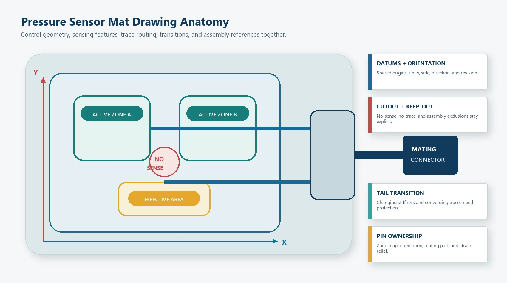
Establish datums and orientation
Define:
- primary X and Y datums;
- top and bottom orientation;
- installation side;
- front/rear or left/right direction;
- connector side;
- critical mounting references;
- drawing units and scale; and
- revision and part-number controls.
Without common datums, the sensing zone, seat feature, cutting tool, and assembly fixture can all be correct relative to different origins and still misalign in production.
Mark the permitted envelope
The permitted envelope is the area where the mat may be placed without interfering with the product. It should account for:
- cushion or housing boundary;
- seams and trim attachments;
- ribs, bosses, clips, holes, and fasteners;
- ventilation or drainage paths;
- moving mechanisms;
- service access;
- high-curvature surfaces;
- cutouts and reliefs;
- adhesive access; and
- the assembly insertion path.
Mark prohibited areas
A prohibited area is not always a hole in the mat. It may be a region where:
- no sensing zone is allowed;
- no trace may pass;
- no adhesive may cover a vent or service feature;
- no stiff transition may sit on a bend;
- no local load may be transferred; or
- additional protection is required.
Show these areas explicitly. Verbal notes such as “avoid the rib” are difficult to inspect.
Define edge and cutout relationships
Edges and internal cutouts can concentrate stress or reduce available trace space. The drawing should identify:
- minimum approved border around active features;
- corner style;
- relief around openings;
- trace keepouts;
- cutting and registration tolerance;
- local support conditions; and
- whether the mat is installed flat or formed.
The exact dimensions depend on the selected construction and manufacturing process. They should come from engineering confirmation rather than a generic online rule.
How Should Sensing Zones Be Laid Out?
A sensing zone must align with the real load path, not merely the center of the visible surface.
Multi-zone array design: carry each sensing zone from load path to software identity.
Map required load cases first
For each required condition, record:
- where the load enters the product;
- how covers, foam, or structures spread it;
- which sensor region should respond;
- which regions may respond without changing the decision;
- which regions must remain inactive; and
- how the controller interprets the result.
This turns the zone layout into a functional map.
Active area, detection area, and physical pad are not always identical
The physical mat may include borders, traces, adhesive, tail transitions, labels, and protective areas that do not sense. The system’s detection area may also be larger than one physical zone because the surrounding material spreads load.
Use separate drawing terms:
overall outline: complete cut shape;active zone: electrical sensing feature;effective detection area: assembly area in which a required load produces the approved response;no-sense area: region that must not create a valid activation;trace corridor: protected route from zone to tail; andtail transition: change from sensor body to flexible interconnect.
Do not use active area to mean all six.
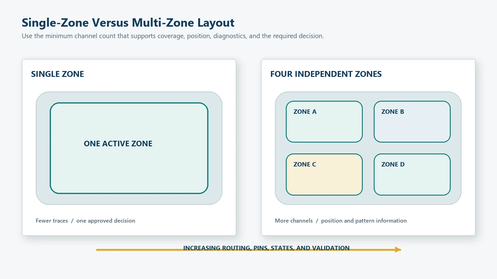
One large zone or several smaller zones?
| Layout | Advantages | Tradeoffs | Appropriate when |
|---|---|---|---|
| One large zone | Fewer traces, pins, and state combinations | Less information about load position; local load path can still create gaps | Any approved load in the area should produce the same result |
| Several independent zones | Position and pattern information; separate diagnostics | More channels, routing, calibration, and failure cases | The controller needs zone-specific decisions |
| Overlapping effective coverage | Can reduce gaps between mechanical load paths | Requires careful logic and assembly validation | Coverage is more important than precise location |
| Small local zone | Compact and simple | Sensitive to position, alignment, and local support | The load path is tightly controlled |
The correct zone count is the minimum that supports the required system decision with adequate margin.
Design for edge and transition cases
Test loads:
- near each active-zone edge;
- between adjacent zones;
- near cutouts and ribs;
- above trace corridors;
- close to the tail transition;
- at expected posture or product-position extremes; and
- in required non-sensing areas.
An edge case can reveal a mechanical gap that is invisible in the electrical drawing.
Design the Mechanical Load Path Before Tuning the Sensor
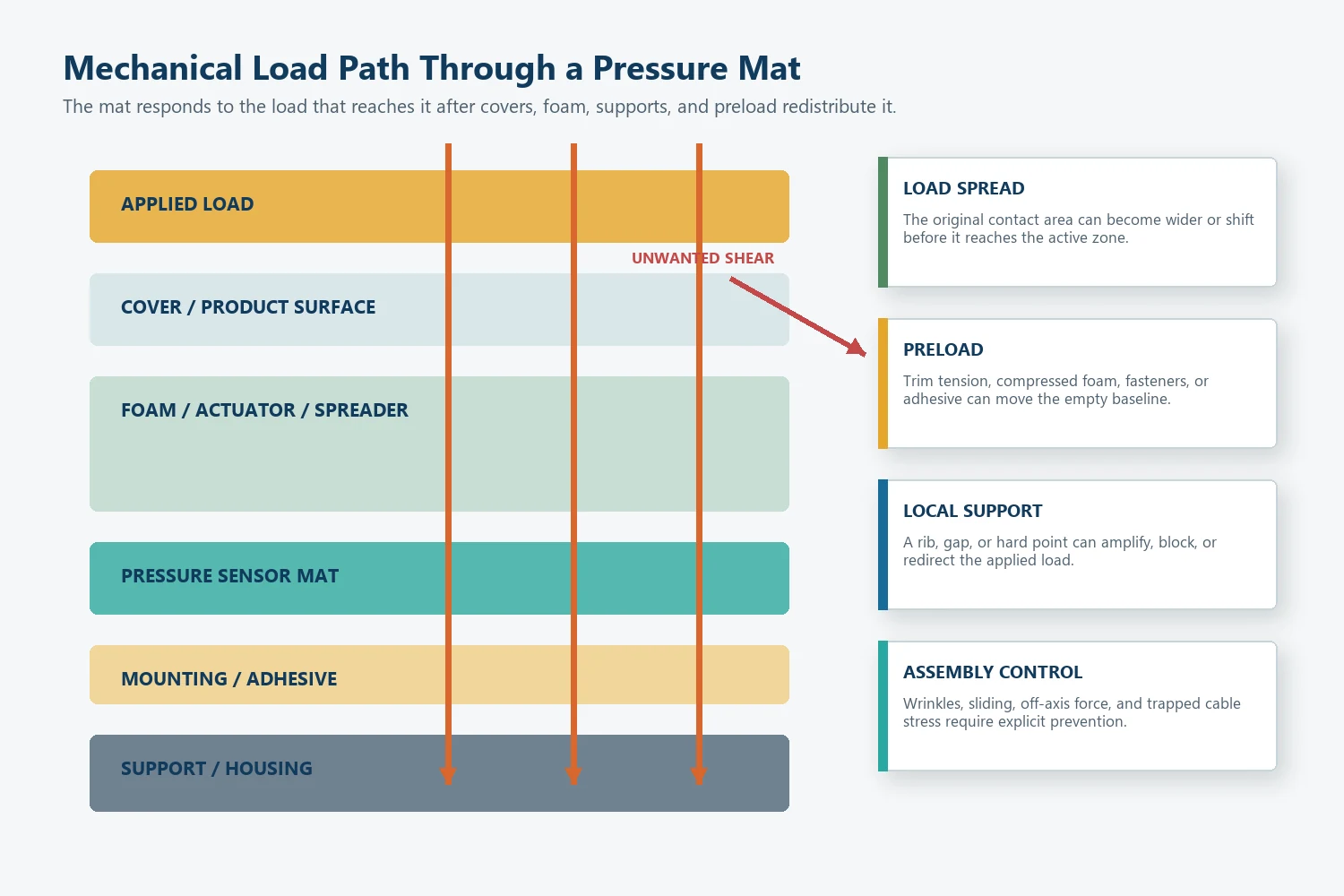
The mat responds to the load that reaches it after the surrounding structure redistributes that load.
User, occupant, or applied load
              |
              v
Cover, upholstery, or product surface
              |
              v
Foam, elastomer, actuator, or load spreader
              |
              v
Pressure sensor mat active zone
              |
              v
Support plate, housing, cushion, or frame
Control the actuator or load spreader
A rigid or semi-rigid actuator can focus load on a sensor area. Foam or a compliant cover can spread load over a wider region. Neither is automatically better.
Review:
- contact area;
- edge shape;
- alignment;
- stiffness;
- travel;
- overtravel;
- angular loading;
- local support;
- tolerance stack; and
- whether the actuator can create shear.
Tekscan’s force-sensor integration guidance emphasizes that the mechanical interface, loading area, alignment, and avoidance of shear or bending at the sensing area affect the result.[3] The same principle applies when integrating a flexible pressure mat, even though the exact JASPER construction may differ.
Separate normal load from shear and peel
Many pressure-sensitive structures are intended to respond to load normal to the sensing plane. Sliding assembly, wrinkled foam, an unsupported cable, or an angled actuator can add shear, peel, or bending.
The design should prevent the mat from becoming a structural hinge, cable restraint, or sliding wear surface unless that use is specifically engineered and validated.
Account for preload
Preload can come from:
- compressed foam;
- trim tension;
- housing screws or snaps;
- mounting adhesive;
- a cover plate;
- cable routing;
- assembly clips; or
- product weight.
Preload changes the empty baseline or contact gap before the target load is applied. Record it in the complete assembly.
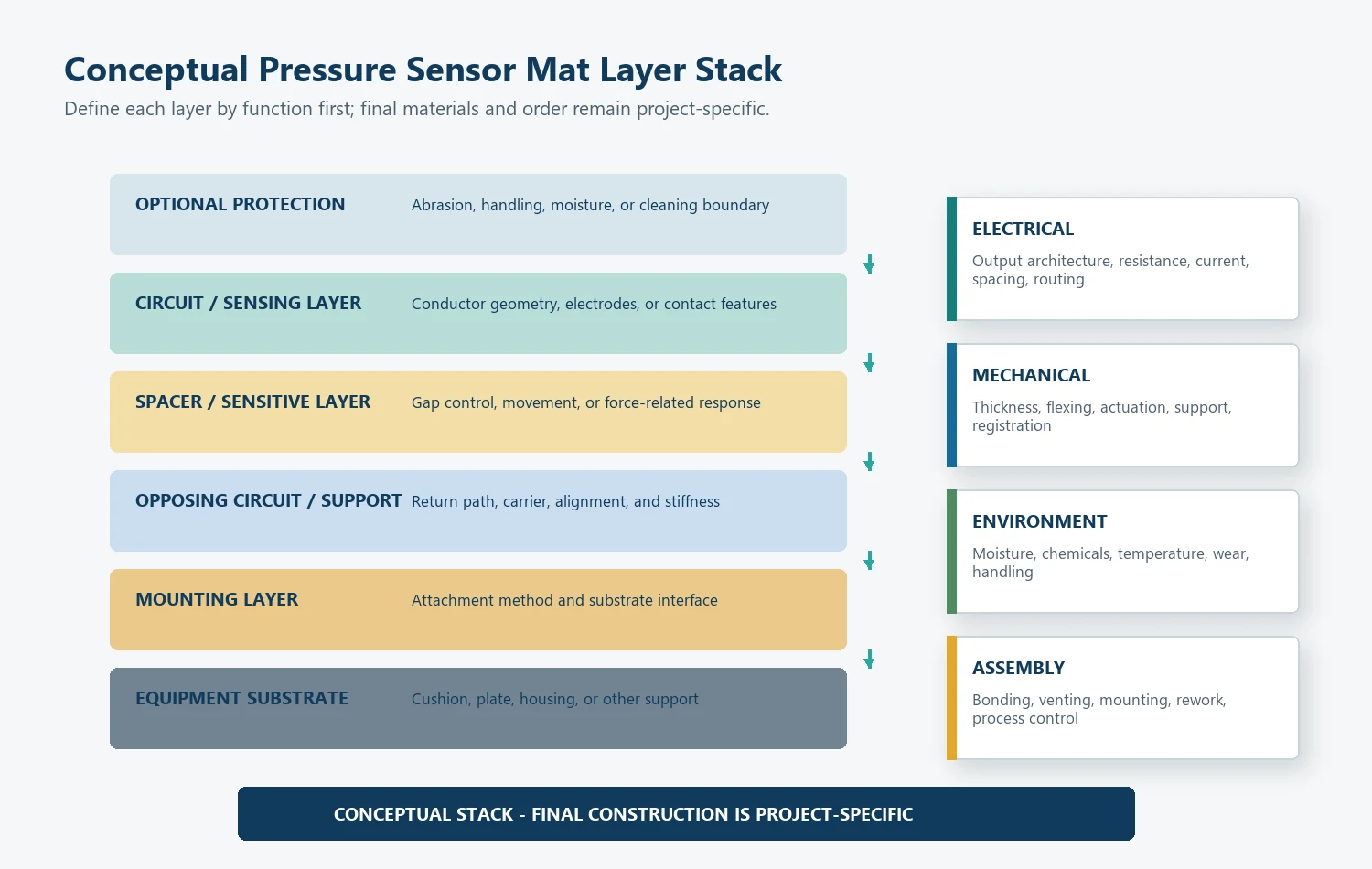
Define the Layer Stack by Function
Do not choose a named film or adhesive before the required functions are clear.
Optional protective or wear layer
Sensing or contact circuit layer
Spacer, gap-control, or force-sensitive layer
Opposing circuit or support layer
Mounting adhesive or attachment feature
Equipment surface or cushion support
The actual order varies by architecture. A contact mat, FSR, printed pressure array, and flexible circuit do not share one universal stack.
| Layer function | Design questions | Typical failure if ignored |
|---|---|---|
| Flexible carrier | How much forming, bending, handling, and dimensional stability are required? | Cracking, distortion, poor fit, or registration shift |
| Conductor or electrode | What current, resistance, geometry, spacing, and routing are required? | Open circuit, excessive resistance, shorts, or zone mismatch |
| Sensing/contact structure | Is the result contact closure or analog force response? | Wrong output behavior or unsupported calibration claim |
| Spacer or gap control | Where may contact occur, and what controls actuation/release? | False activation, no activation, or inconsistent switching |
| Bonding layer | Which internal areas need lamination and which need movement or venting? | Delamination, restricted movement, contamination, or response shift |
| Protective layer | What abrasion, moisture, handling, or chemical exposure exists? | Damage during assembly or use |
| Mounting layer | Which surface receives the mat, and must it be removable or permanent? | Lift, wrinkle, trapped stress, or service problem |
Materials should be confirmed after the electrical, mechanical, environmental, process, and documentation requirements are known.
How Should Conductors, Traces, and Tail Routing Be Designed?
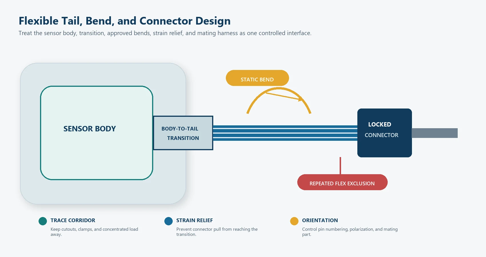
The tail is part of the sensor, not an afterthought added after the zones are complete.
Select the exit location early
The exit location affects:
- available trace corridors;
- assembly direction;
- connector location;
- bend count;
- strain relief;
- protection from moving mechanisms;
- cable length; and
- the overall cut shape.
Moving the connector late in the project can force a complete reroute.
Distinguish static and dynamic flexing
A tail that bends once during assembly has a different duty from a tail that moves during every operating cycle. State which condition applies.
For each bend, record:
- bend location;
- direction;
- forming sequence;
- repeated or one-time movement;
- adjacent stiff regions;
- support and strain relief;
- possible rubbing; and
- inspection access.
IPC-2223 provides design guidance for flexible printed boards and flex interconnect structures.[4] Use it where the construction and customer requirement make it applicable. Do not claim IPC compliance for every printed sensor mat without a confirmed standard and drawing scope.
Protect the body-to-tail transition
The transition often combines:
- changing stiffness;
- converging traces;
- local bending;
- adhesive edges;
- cover-layer ends;
- assembly handling; and
- connector pull.
Keep uncontrolled folds, sharp hardware edges, clamps, and concentrated loads away from this region. Interlink’s FSR integration guidance similarly warns against kinking or sharply bending the tail and recommends protection from mechanical damage.[2]
Define connector and pin ownership
The drawing package should include:
- connector manufacturer and part number when approved;
- mating connector;
- pin count;
- pin numbering orientation;
- zone-to-pin map;
- common-return structure if used;
- wire or tail length;
- locking and polarization;
- strain relief;
- insertion and service requirements; and
- continuity or resistance checks.
Connector compatible is not a complete interface specification.
Lamination, Registration, and Cut Geometry
Pressure sensor mats depend on layer alignment. A small shift can move a contact, reduce a trace clearance, cover a vent path, or change the active-zone border.
The manufacturing drawing should identify:
- which dimensions control individual layers;
- registration datums;
- active-feature-to-cut-edge relationships;
- spacer-to-contact alignment;
- tail-layer alignment;
- adhesive keepouts;
- internal cutouts;
- allowed cosmetic conditions;
- label location; and
- inspection method.
Tolerance stack matters
Do not assign the same tolerance to every feature. Classify dimensions by function:
critical: affects sensing, connector fit, or assembly;important: affects routing, alignment, or protection;reference: communicates context but is not directly inspected.
Then evaluate the combined worst-case condition. A zone can be within its own tolerance while the seat feature, die cut, spacer, and mounting position combine to move the effective detection area outside the approved load path.
Internal movement may be necessary
Some structures need controlled movement, air displacement, or contact travel. Bonding every internal surface can change actuation behavior. Conversely, leaving an unintended unbonded region can allow contamination, wrinkles, or layer migration.
The layer drawing should show bonded, unbonded, vented, and protected regions where relevant.
Mounting and Assembly Design
A good sensor design can be damaged by an uncontrolled installation process.
Define the mounting surface
Record:
- substrate material;
- surface texture;
- curvature;
- cleanliness;
- coating or release agents;
- temperature during installation;
- access for pressure application;
- rework requirement; and
- expected environmental exposure.
Pressure-sensitive adhesive performance depends on the exact adhesive, substrate, preparation, application pressure, and conditions. 3M’s bonding guidance treats surface preparation as substrate-specific.[5] The mat drawing should therefore reference the approved material and process, not a generic instruction copied from another adhesive.
Control wrinkles and trapped stress
The assembly method should avoid:
- folds through active zones;
- wrinkles;
- stretching the mat to make it fit;
- trapped cable tension;
- bridging over unsupported gaps;
- adhesive contact before alignment;
- rubbing at a cut edge; and
- using the tail to pull the body into position.
Use assembly fixtures or alignment features when manual placement cannot reliably hold the critical position.
Plan service and replacement boundaries
OEM equipment may require a non-serviceable bonded mat, a replaceable module, or a sensor integrated into a cushion. Define the intended service level before selecting permanent adhesive, hidden connectors, or irreversible assembly steps.
This is a product-design decision, not a consumer repair instruction.
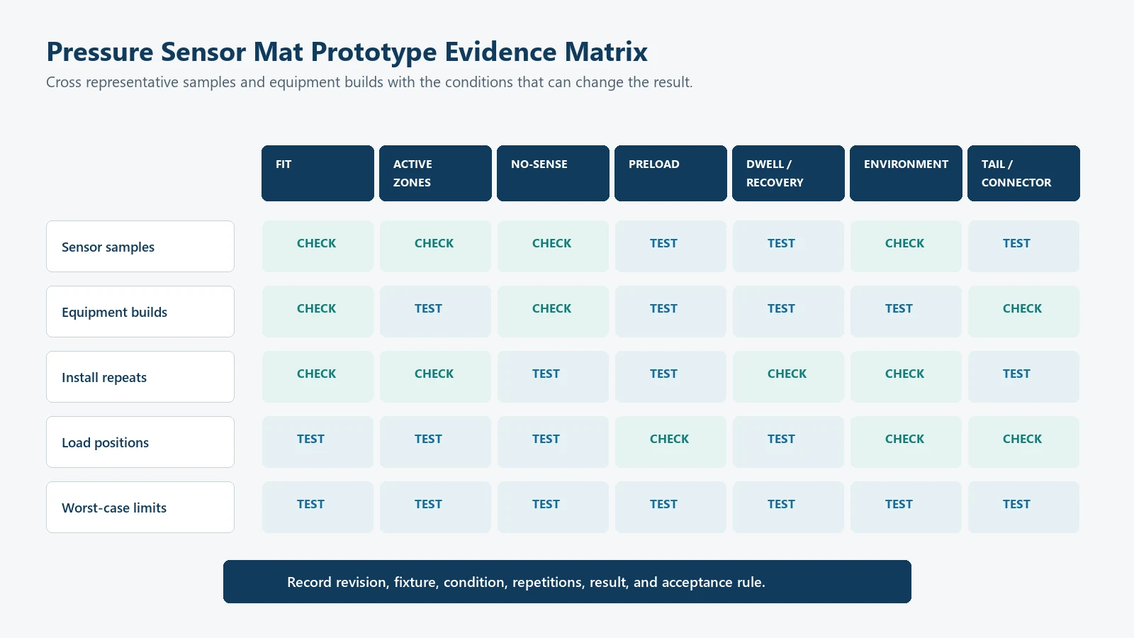
Prototype the Mechanical and Electrical System Together
The purpose of a prototype is to expose uncertain relationships before production tooling and documentation are fixed.
JASPER’s prototyping capability can support drawing review and sample iteration after the project inputs are confirmed.
Prototype stage 1: geometry and fit
Check:
- overall outline;
- cutouts and forbidden features;
- zone alignment;
- tail exit;
- connector access;
- assembly direction;
- mounting surface;
- flatness and forming; and
- interference with the product.
Electrical output is useful, but the main question is whether the design physically belongs in the assembly.
Prototype stage 2: functional response
Test:
- required active-zone load cases;
- required no-sense cases;
- edges and zone gaps;
- loading and unloading;
- preload;
- dwell and recovery;
- contact bounce or analog stability;
- trace and connector continuity; and
- the real controller interface.
The separate pressure sensor mat calibration guide explains how threshold distributions, hysteresis, debounce, guard bands, and acceptance logic should be developed after the mechanical stack is stable.
Prototype stage 3: variation and abuse
Add:
- multiple mats;
- multiple equipment or cushion builds;
- repeated installation;
- alignment extremes;
- environmental conditioning;
- cable and connector handling;
- repeated cycles;
- concentrated or off-axis loads; and
- approved fault cases.
NIST measurement-process guidance separates repeatability, longer-term variability, calibration, bias, gauge studies, and uncertainty.[6] Use those categories to organize evidence instead of reporting only an average from one sample.
Design review output
The prototype stage should close with:
- approved drawing revision;
- approved layer and material list;
- zone-to-pin map;
- approved assembly method;
- critical-to-function dimensions;
- prototype test report;
- open risk list;
- change-control triggers;
- production inspection plan; and
- responsibility split between supplier and system owner.
Application Examples and Design Priorities
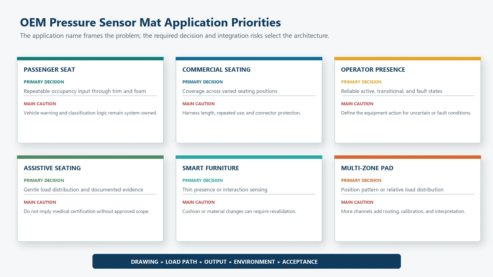
| OEM application | Primary design priority | Useful architecture | Main caution |
|---|---|---|---|
| Automotive passenger-seat occupancy | Repeatable detection through foam and trim | Contact or analog mat matched to the seat system | Final warning, classification, and vehicle logic remain system-owned |
| Rear or commercial-vehicle seating | Coverage, routing, repeated use, connector protection | Single or multi-zone mat | Long harness paths and variable seating positions increase integration risk |
| Operator-presence seat | Reliable active/inactive decision and fault handling | Contact mat or analog threshold | Define what the equipment does during transitional or fault states |
| Medical or assistive seating input | Gentle load distribution, cleaning exposure, and documented validation | Contact, analog, or multi-zone mat | Do not imply medical certification without an approved project scope |
| Smart furniture or occupancy monitoring | Thin integration and acceptable false/missed decisions | Contact or analog mat | Cushion replacement or material change may require revalidation |
| Position or load-distribution pad | Zone coverage and channel mapping | Multi-zone analog or contact array | More zones require more electronics, calibration, and data interpretation |
| Industrial safety edge or area mat | Coverage, environmental protection, and fail-safe system design | Purpose-designed contact or pressure-sensitive mat | A seat sensor design should not be reused without application-specific safety review |
For automotive equipment, treat the pressure mat as one component inside the seat and vehicle system. For other equipment, identify the equivalent system owner, risk analysis, controller, and validation boundary.
Related validation: See test planning for a pressure sensor mat design.
Pressure Sensor Mat Design Review Matrix
Use this matrix before releasing a prototype drawing.
| Review area | Confirmed input | Evidence required | Owner |
|---|---|---|---|
| System decision | States, signal, zones, timing, and fault behavior | Requirement or interface specification | OEM/system owner |
| Mechanical envelope | Datums, outline, cutouts, prohibited areas, stack | CAD, section drawing, or representative sample | Mechanical team |
| Load path | Required loads, positions, contact area, spreader, support | Load map or fixture plan | Mechanical/system team |
| Sensing layout | Active zones, no-sense areas, effective coverage | Zone drawing and edge-case plan | Sensor and system teams |
| Electrical interface | Contact/analog type, circuit, pins, diagnostics | Schematic and zone-to-pin map | Electrical team |
| Tail and connector | Exit, bends, length, mating part, strain relief | Harness and assembly drawing | Electrical/mechanical teams |
| Materials and layers | Functional stack, environment, bonding, protection | Approved material list and supplier data | Sensor/material teams |
| Assembly | Placement, surface preparation, fixtures, inspection | Work instruction or assembly trial | Manufacturing team |
| Validation | Samples, repetitions, conditions, acceptance | Approved test matrix | Quality/system team |
| Change control | Features that trigger review or revalidation | Controlled change list | Program owner |
Any blank owner is a project risk. A requirement without an owner usually becomes a late prototype argument.
Common Pressure Sensor Mat Design Mistakes
Drawing only the outside shape
The outline does not define zones, no-sense areas, traces, layer alignment, tail transition, connector orientation, mounting, or the load path.
Placing zones by visual symmetry
The product may look symmetrical while the foam, support, user posture, or actuator creates an asymmetrical load path.
Routing the tail after every other feature is fixed
A late tail route can cross active areas, sharp edges, moving parts, or forbidden bends and can force a new connector location.
Treating all flexible areas as bendable
The sensor body, active zone, body-to-tail transition, stiffener, connector, and tail can have different bending limits.
Choosing materials from a generic stack
A material that works in one dry, flat, static application may not fit a curved, humid, cleaned, high-cycle, or serviceable assembly.
Calibrating before the mechanics are stable
Thresholds and analog relationships can change when the zone, actuator, foam, support, adhesive, or mounting position changes.
Approving one center-load result
The required application may include edge loads, position changes, loading and unloading, dwell, multiple builds, and environment.
Adding channels without a decision rule
More zones add cost and failure cases. Each zone needs a defined purpose and interpretation.
Ignoring manufacturing registration
An electrical design can be correct while die cutting, spacer alignment, printing, and mounting tolerances shift the effective sensing area.
What Should an OEM Send for Design Review?
Provide:
- Product or seat drawing with datums, units, and revision.
- Available sensor envelope, cutouts, and prohibited regions.
- Installation section showing cover, foam, actuator, support, adhesive, and mat.
- Required active, inactive, transitional, and fault conditions.
- Load cases, contact areas, directions, positions, dwell, and repetition.
- Required contact, analog, multi-zone, or conditioned output.
- Sensing-zone purpose and effective coverage requirement.
- Tail exit, routing, bend locations, cable length, and strain-relief concept.
- Connector and mating-part drawing, pinout, and zone map.
- Circuit, supply, ADC or digital input, thresholds, timing, and diagnostics.
- Environmental, cleaning, lifecycle, assembly, and handling conditions.
- Prototype quantity, product samples, fixtures, schedule, and acceptance plan.
- Annual volume, traceability, label, packaging, and documentation requirements.
Mark unknown items as open. A controlled open item is easier to resolve than an assumed value hidden in a drawing.
Frequently Asked Questions
What information is needed to design a pressure sensor mat?
Start with the required system decision, available envelope, load path, active and no-sense zones, output type, mechanical stack, tail route, connector, environment, prototype plan, and acceptance method.
Is the active area the same as the overall mat size?
No. The overall mat also includes borders, traces, adhesive, protection, labels, cutouts, tail transitions, and other non-sensing features. The effective detection area can also differ from the electrical zone because the surrounding mechanics spread load.
How many sensing zones should a mat use?
Use the fewest zones that support the required system decision with adequate coverage and diagnostics. Additional zones add traces, connector pins, channels, calibration, and validation cases.
Can a pressure sensor mat bend?
Some parts may flex, but the allowable bend depends on the construction and location. The active area, tail, body-to-tail transition, stiffener, and connector can have different limits. State whether each bend is one-time or repeated.
Should the mat be calibrated before installation?
Component checks can be performed before installation, but final thresholds or load relationships should be validated in the representative mechanical stack and real measurement circuit.
Which adhesive should be used?
There is no universal adhesive. Selection depends on the carrier, mounting substrate, surface texture, environment, assembly process, removal requirement, and effect on sensor mechanics. Use approved supplier data and validate the complete assembly.
Can one mat design be reused in several products?
Only after confirming that the load path, envelope, mounting, tail route, electronics, required states, and validation conditions remain equivalent. A similar outline does not prove functional equivalence.
Submit a Pressure Sensor Mat Design Package
Send the product drawing, installation section, active and prohibited areas, output requirement, load cases, tail route, connector, environment, prototype quantity, and acceptance plan through the JASPER RFQ form. The first review should resolve the design envelope and load path before materials and thresholds are frozen.
Sources
- JASPER Electronics, “Seat Occupancy Sensor Mat.” https://www.jasperele.com/products/car-seat-occupancy-sensor/seat-occupancy-sensor-mat/
- Interlink Electronics, “FSR 400 Series Integration Guide.” https://www.interlinkelectronics.com/downloads/integration-guides/fsr-400-series-integration-guide.pdf
- Tekscan, “FlexiForce Integration Guides,” mechanical integration and loading guidance for thin-film force sensors. https://www.tekscan.com/resources/datasheets-guides/flexiforce-integration-guides
- IPC, IPC-2223E: Sectional Design Standard for Flexible/Rigid-Flexible Printed Boards. https://shop.ipc.org/ipc-2223/ipc-2223-standard-only/Revision-e/english
- 3M, “3M VHB Tape Surface Preparation Technical Bulletin.” https://multimedia.3m.com/mws/media/66019O/vhb-tm-tape-surface-preparation-technical-bulletin.pdf
- NIST/SEMATECH, e-Handbook of Statistical Methods, “Measurement Process Characterization.” https://www.itl.nist.gov/div898/handbook/mpc/mpc.htm