Wie funktionieren Folientastaturen?
A membrane switch works by closing an electrical Schaltung when pressure on the printed key area moves a Kontakt layer or metal dome through a spacer opening.
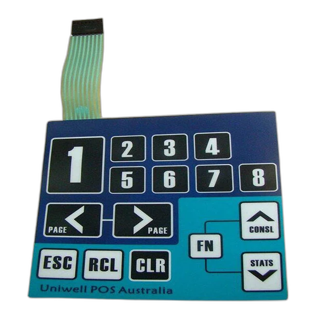
The technical reference explains the physical action simply enough for buyers, but with enough engineering detail to help define layer stack, tactile feel, connector routing, and sample approval requirements.
Quick answer: pressure closes a controlled electrical path.
A membrane switch works when pressure on the front overlay closes a Schaltung through a Kontakt layer or metal dome. The spacer keeps Kontakts separated until Betaetigung, while printed traces, the tail, and the connector carry the signal to the product electronics.
Was passiert when a key is pressed?
The sequence is simple, but each layer has to support the same motion, electrical path, and return behavior.
The user presses a defined key area on the graphic overlay. The visible overlay is not only decoration; it is the touch surface that guides the press.
The overlay and upper switch layer move downward in the active key zone. Key size, overlay thickness, embossing, and support from the enclosure affect this movement.
The spacer keeps the Kontakts apart in the resting state. At the key opening, the structure allows controlled movement toward the Schaltung Kontakt.
A conductive Kontakt area or metal dome meets the lower Schaltung Kontakt. This closes the electrical path for that key or matrix position.
The signal travels through printed traces, a flexible tail, and the connector system toward the product electronics.
The controller reads the closed Schaltung as an operator input, LED command, keypad signal, or other defined function.
After the press is released, the dome, film, and spacer return the key to its resting open position.
Which layers make the switch work?
A membrane switch is a stack. The Schaltung does not work correctly unless the overlay, spacer, Kontakt, tail, adhesive, and enclosure support each other.
| Layer or area | Role in the working principle | Design details to confirm |
|---|---|---|
| Graphic overlay | Provides the visible press surface and protects the printed legends | Material, thickness, finish, embossing, window areas, cleaning exposure |
| Overlay adhesive | Bonds the front layer to the switch stack without blocking key motion | Adhesive type, lamination quality, bubbles, edge condition, material compatibility |
| Spacer layer | Keeps Kontakts separated until the key area is pressed | Spacer thickness, opening size, registration, venting path, sealing path |
| Metal dome or upper Kontakt | Moves downward to close the Schaltung and may create tactile click feedback | Dome force, dome diameter, Kontakt stability, snap ratio, support surface |
| Lower Schaltung Kontakt | Receives the moving Kontakt and completes the electrical path | Conductive ink, PCB/FPC support, Kontakt size, oxidation and contamination control |
| Printed traces and matrix | Carry the signal from each key area toward the tail | Trace width, matrix layout, common lines, LED routing, short/open test plan |
| Tail und Steckverbinder | Transfer the signal to the product electronics | Tail length, exit direction, pitch, pinout, Kontakt side, stiffener, bend radius |
| Rear adhesive and enclosure | Hold the assembly in place and support the pressing action | Housing material, surface texture, installation pressure, gasket or sealing needs |
Why some Folientastaturen click and others do not
The electrical idea is the same: close the Schaltung. The user feel changes depending on the Kontakt structure and mechanical support.
| Type | How it works | When buyers choose it |
|---|---|---|
| Tactile membrane switch | A metal dome or formed feature snaps down and closes the Kontakt, giving a noticeable click | When operators need press confirmation by feel, such as control panels, keypads, and industrial equipment |
| Non-tactile membrane switch | The Kontakt closes without a strong mechanical click, often creating a flatter and quieter press | When a low-profile surface, simple interface, or softer feel is preferred |
| Metal dome membrane switch | A stainless steel dome controls snap feel, Betaetigung force, and Kontakt closure | When consistent key feel and defined force are important in sample approval |
| PCB/FPC supported switch | The Schaltung or connector area uses PCB or FPC support for routing or stability | When the electronics interface, LED routing, or connector area needs more structure |
What changes the press feel and signal reliability?
A bench sample can close the Schaltung, but the real product depends on the complete stack and the enclosure behind it. These details should be checked before production approval.
- Overlay thickness and material affect flexibility and operator feel.
- Dome force, dome size, and support surface affect tactile click and return.
- Spacer thickness and opening accuracy affect travel and Kontakt timing.
- Tail exit direction and bend radius affect trace stress during assembly.
- Connector pitch, pinout, Kontakt side, and stiffener affect installation reliability.
- Adhesive and enclosure flatness affect how the key area is supported.
- Backlighting, LED windows, and dead-front icons add opacity and alignment requirements.
- Waterproof or cleanable designs need sealing review beyond the switch Schaltung.
RFQ note: Send the drawing, artwork, Schaltung or pinout, connector requirement, tail route, key feel target, enclosure material, and application environment. A switch can work electrically but still fail assembly if the tail, adhesive, or enclosure support is wrong.

Common design variations that change how the switch is built
The working principle stays similar, but the stack changes when lighting, sealing, connector, or Schaltung support requirements are added.
LED and backlit versions
LED indicators, backlit icons, and light guide films require Schaltung routing, opacity control, and window alignment to be reviewed together.
Waterproof versions
Sealing depends on overlay continuity, adhesive bonding, edge design, tail exit, enclosure support, and project-specific exposure.
PCB/FPC versions
PCB or FPC support can help with dense Schaltungs, LEDs, connector stability, or rigid areas behind the interface.
Embossed key versions
Rim embossing or key embossing can help users locate buttons, but it changes feel, forming limits, and stack behavior.
Dead-front graphics
Hidden icons appear only when lit, so printing opacity, LED position, and light blocking become part of the working design.
Custom connector versions
ZIF, crimp, pin header, solder pad, and custom tail options change assembly method, test plan, and serviceability.
When a membrane switch does not work as expected
Failure symptoms usually point to a layer, connector, assembly, or environment issue. Use these symptoms to describe the problem more clearly during troubleshooting.
| Symptom | Possible cause | Was zu pruefen ist |
|---|---|---|
| No signal from a key | Open trace, wrong pinout, poor connector Kontakt, Kontakt contamination | Continuity test, pinout, connector insertion, Kontakt side, short/open report |
| Wrong signal or swapped keys | Matrix or pinout mismatch between switch and electronics | Circuit drawing, controller mapping, tail orientation, connector numbering |
| Intermittent signal | Sharp tail bend, unstable ZIF insertion, weak Kontakt, enclosure stress | Bend radius, stiffener thickness, strain relief, full assembly test |
| Weak or inconsistent click | Dome force, spacer height, overlay thickness, support surface, adhesive stack | Actuation force review, dome selection, enclosure backing, sample comparison |
| LED or icon not aligned | LED position, window tolerance, printing registration, light guide placement | Artwork revision, LED layout, window tolerance, opacity/light blocking |
| Water or cleaning failure | Edge path, tail exit, adhesive mismatch, enclosure sealing problem | Sealing path, adhesive choice, housing surface, exposure requirement |
Continue from the working principle
Verwandte Ressourcen cover product selection, connector design, switch types, and RFQ preparation.
Detailed questions about how Folientastaturen work
Do all Folientastaturen click?
No. Taktile Folientastaturen usually use metal domes or formed structures to create a click response. Nicht-taktile Folientastaturen close the Schaltung without the same mechanical feedback.
How does a membrane switch connect to electronics?
Most designs use a flexible tail with a ZIF connector, crimp connector, pin header, solder pad, PCB/FPC support, or a custom connector. Pitch, pinout, Kontakt side, stiffener, and bend radius should be defined before sampling.
Can a membrane switch include LEDs or backlighting?
Yes. LED indicators, backlit icons, light guide films, and dead-front graphics can be integrated when the Schaltung, printing opacity, spacer, and window design are reviewed together.
What keeps the Schaltung open before the key is pressed?
The spacer layer and Kontakt geometry keep the conductive areas separated. The Schaltung closes only when pressure moves the Kontakt area through the spacer opening.
Why does key feel change between samples?
Key feel can change because of dome force, overlay thickness, spacer thickness, key size, embossing, adhesive stack, PCB/FPC support, and the enclosure behind the switch.
Is the working principle different for wasserdichte Folientastaturen?
The Schaltung closure principle is the same, but waterproof designs must also review edge sealing, adhesive bonding, tail exit, enclosure support, and exposure conditions.
Can JASPER review an existing switch and explain how it works?
Yes. A sample, photo, drawing, Schaltung note, connector information, and known failure symptoms can be reviewed to identify the likely stack and working path.
What should be confirmed before production?
Confirm the layer stack, key layout, tactile or non-tactile feel, Schaltung, pinout, connector, tail route, adhesive surface, environment, backlighting, inspection method, and sample approval criteria.
Planning a switch structure or troubleshooting a sample?
Send your drawing, sample photo, Schaltung notes, connector requirement, and application environment. JASPER can review the Schaltung path, stack-up, connector route, and sample risks before production.
Technische Pruefung anfordern