
Sealing, Spacer and Gasket Materials
A sealed membrane interface is a system of controlled gaps, bonds, compression zones, tail exits, vents, liners, and enclosure surfaces. The membrane switch spacer material creates functional cavities; perimeter seals limit ingress paths; gaskets manage the joint with the enclosure; tail-exit details close a difficult transition; and vents control trapped air or pressure change. No material by itself creates or guarantees an IP rating.
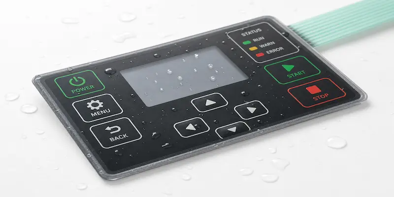
Quick Selection Facts
Sealing begins with the actual exposure and assembly, not with a generic request for a waterproof adhesive or foam gasket.
| Review input | Engineering question | Useful RFQ information |
|---|---|---|
| Exposure | Is the interface exposed to dust, splash, cleaning, water contact, or weather? | Environment and required validation |
| Enclosure joint | Where can liquid or dust travel between the interface and enclosure? | Enclosure section and outline |
| Compression | What creates and maintains gasket compression? | Geometry and assembly sequence |
| Tail exit | Where does the tail leave the protected area? | Tail path, bend, connector, and opening |
| Venting | Must air move around a tactile cavity or sealed volume? | Key layout and pressure-change concern |
| Cleaning | What contacts the edge, gasket, adhesive, and enclosure? | Chemicals, method, and frequency |
| Mounting surface | Is the enclosure smooth, textured, painted, curved, or interrupted? | Substrate and surface condition |
| Assembly | Who positions, compresses, and verifies the seal? | Work sequence and responsibility |
These inputs interact. A continuous perimeter can still fail at the tail, a gasket needs maintained compression, and an uncoordinated vent may become an ingress path.
Material and Construction Options
The following options describe engineering roles, not a confirmed JASPER catalog. Exact foam, gasket, adhesive, liner, and vent materials must be checked against current availability, supplier evidence, the drawing, and project validation.
| Layer or construction | Primary role | Why it may be considered | Boundary to review |
|---|---|---|---|
| Spacer adhesive or laminate | Creates switch cavities and separates circuit layers | Geometry around keys, contacts, LEDs, or vents | Adhesive behavior, cut accuracy, ooze, and alignment |
| Foam-supported gasket | Fills an enclosure joint through compression | Irregular joints needing compliance | Compression, recovery, surface, fasteners, and environment |
| Solid gasket or elastomeric layer | Creates a defined sealing or isolation interface | Joints with a designed compression path | Compatibility, cut geometry, and assembly load |
| Perimeter seal | Interrupts ingress around the interface boundary | A continuous protected area | Corners, seams, cutouts, edge distance, and bond continuity |
| Tail-exit seal | Controls the transition where the tail leaves the sealed area | A common weak point in the stack | Step, bend, strain, coverage, slot, and assembly access |
| Release liner | Protects adhesive until assembly | Clean handling and controlled placement | Split, removal direction, and exposed adhesive |
| Vent path or feature | Allows air movement or pressure equalization | Tactile cavities or changing pressure | Route, contamination, exposure, blockage, and termination |
| Project-specific alternative | Addresses unusual geometry or exposure | Only after evidence review | Do not infer availability or performance |
A spacer establishes internal switch geometry; a gasket usually manages an external joint or compression interface. One layer may support both roles only when the complete stack and assembly method allow it.
Seal-System Decisions
Map a continuous perimeter and mark every interruption: tail exit, fastener, window, connector opening, cavity, edge step, and enclosure seam. One small discontinuity may dominate the result.
Give the tail exit its own cross-section. The thickness step may create a path, so coordinate support, bend, adhesive coverage, strain relief, enclosure opening, and seal termination.
The mechanical design must create and maintain compression. A gasket cannot compensate indefinitely for warpage, poor fastener spacing, uneven load, or an undefined stop. Too little may leave a path; too much may distort the interface or displace adhesive.
Adhesive bonding depends on the enclosure surface. Texture, paint, contamination, curvature, low-surface-energy plastic, and surface variation can prevent complete contact. Review these factors with the pressure-sensitive adhesive material selection rather than treating spacer adhesive as universally compatible.
Vents require a safe destination. A channel ending at an exposed edge may become an ingress route, while blocking all air paths may affect tactile or pressure behavior. Coordinate the vent across the complete stack and enclosure.
Environmental Inputs
Translate broad terms such as waterproof, washdown, outdoor, or chemical resistant into observable conditions. State whether exposure is dust, splash, directed spray, repeated cleaning, temporary immersion requirement, outdoor cycling, condensation, or pressure change. Include the direction of exposure and the joints most likely to see it.
Cleaning can attack more than the visible overlay. Fluid may reach the perimeter adhesive, tail seal, gasket, printed edge, or enclosure finish. Provide the actual cleaning agents and application method when possible. A wipe, mist, spray, and soak are different boundary conditions even when the same chemical is named.
Temperature requirements affect the full assembly, including material expansion, adhesive behavior, gasket compression, enclosure movement, and pressure within sealed cavities. This page does not provide a universal range because the relevant limits depend on the confirmed materials and construction.
Outdoor exposure adds ultraviolet light, water, temperature cycling, dirt, and changing pressure. See outdoor material and exposure considerations for the broader material discussion. The sealing page remains focused on paths, joints, and construction layers.
Manufacturing Implications
Die cutting controls the perimeter, spacer pockets, vents, tail details, and alignment. The drawing should distinguish adhesive, cavities, vent paths, liner splits, and inspection datums.
Lamination sequence matters. Misalignment can narrow a seal, block a vent, or move the tail seal. Contamination can interrupt bond lines, so liner removal should expose only the adhesive needed for each step.
Seams, corners, overlaps, and joints are part of the seal design. Compression must occur in the intended zone, sometimes with an enclosure stop or controlled fastener pattern.
Inspection can include visual continuity, alignment, edge condition, contamination, liner removal, gasket placement, tail transition, vent location, and assembled fit. Any environmental or ingress test must follow the project’s defined requirement and approved method. Refer to environmental and assembly validation without assuming that an unverified test or rating applies to every construction.
Common Failure Modes
| Symptom | Likely areas to inspect | Corrective direction |
|---|---|---|
| Perimeter leak | Gap, seam, corner, cutout, contamination, insufficient bond area | Re-map the continuous seal path and improve the local joint |
| Loss of gasket compression | Enclosure movement, fastener spacing, material recovery, undefined stop | Redesign the mechanical compression path |
| Tail leakage | Stack step, incomplete adhesive coverage, slot geometry, tail movement | Create a dedicated tail-exit section and support the transition |
| Blocked vent | Adhesive flow, liner debris, misregistration, enclosure contact | Protect and inspect the intended vent route |
| Edge lift | Surface incompatibility, contamination, curvature, stress, inadequate wet-out | Review substrate, preparation, adhesive, and edge geometry |
| Contamination in the seal | Dust, fibers, oils, exposed adhesive, poor liner handling | Improve handling sequence and inspection |
| Adhesive ooze | Construction, pressure, heat, cut geometry, excessive compression | Reassess the adhesive and mechanical stack |
| Enclosure mismatch | Warpage, texture, step, radius, unsupported gap | Design the interface around measured enclosure geometry |
Alternatives and Design Boundaries
A material alone cannot create, certify, or guarantee an IP rating. An ingress result belongs to the assembled product and depends on enclosure design, interfaces, fasteners, compression, tail exit, vents, manufacturing, and the applicable validation method. A supplier statement about a foam, film, or adhesive is not a substitute for testing the finished construction against the required condition.
Use understand IP65 and IP67 design requirements when the project needs rating-oriented guidance. Use waterproof membrane switch enclosure and seal design for a system-level design review. Those resources own the rating and enclosure intent; this page explains the material and layer functions.
Some joints are better solved mechanically than with more adhesive. A bezel, enclosure pocket, controlled compression stop, fastener change, molded feature, or protected tail route may produce a more stable design. The correct alternative depends on service access, replaceability, enclosure tolerances, and assembly responsibility.
No universal water, dust, washdown, chemical, compression, temperature, venting, or service-life performance is claimed here. Exact public wording requires verified material evidence and project-specific results.
Related Products, Testing and Applications
For a commercial assembly, review sealed and waterproof membrane switch constructions. Marine and outdoor equipment may add exposed edges, washdown, weather, and pressure changes; see sealing layers for marine and outdoor interfaces without assuming that any material alone satisfies an ingress requirement.
Related paths:
- Materials for custom interface products
- Pressure-sensitive adhesives for custom interfaces
- Waterproof membrane switch design
- IP65 versus IP67 membrane switch requirements
- Outdoor membrane switch material considerations
- Environmental and assembly validation
Engineering FAQ
Does a waterproof gasket make a membrane switch IP rated?
No. An IP rating applies to the tested assembly and defined condition. Enclosure, perimeter, tail exit, venting, compression, fasteners, manufacturing, and test method all contribute.
What is the difference between a spacer and a gasket?
A spacer creates internal cavities and separates functional layers. A gasket manages an interface-to-enclosure joint through contact or compression. One construction may support both, but the drawing should define each function.
Why is the tail exit a common sealing concern?
The flexible tail creates a thickness transition through the protected perimeter, introducing a step, bend stress, incomplete contact, or enclosure opening. Review it as a dedicated cross-section.
Should every sealed switch have a vent?
Not necessarily. Vent need, path, termination, and protection depend on the tactile construction, enclosure, pressure conditions, and exposure. A required air path still needs a protected destination.
What should I send for a sealing-material review?
Send the enclosure drawing, interface outline, target ingress or cleaning condition, tail path, mounting surface, fastener or bezel arrangement, vent needs, chemicals, temperature requirement, assembly sequence, and required validation method.
Define the Exposure Before Selecting the Seal
For an RFQ review, provide the target ingress requirement, enclosure drawing, mounting surface, tail exit, fastener or bezel arrangement, washdown or immersion condition, cleaning chemicals, temperature requirement, vent needs, assembly sequence, and requested validation. Photos or samples of the actual enclosure are useful when texture, flatness, or edge steps are difficult to communicate in a drawing.
Share washdown, enclosure and sealing requirements
Review the Complete Stack Before Tooling
Share the drawing, enclosure, operating conditions, assembly process, approval evidence, quantity, and timing. Unknown values can remain open items; they should not become assumed guarantees.