SMT 対応 · IPC-6013 フレックス · ピン配置に合わせて構築
PCB and FPC メンブレンスイッチ for OEM Interfaces
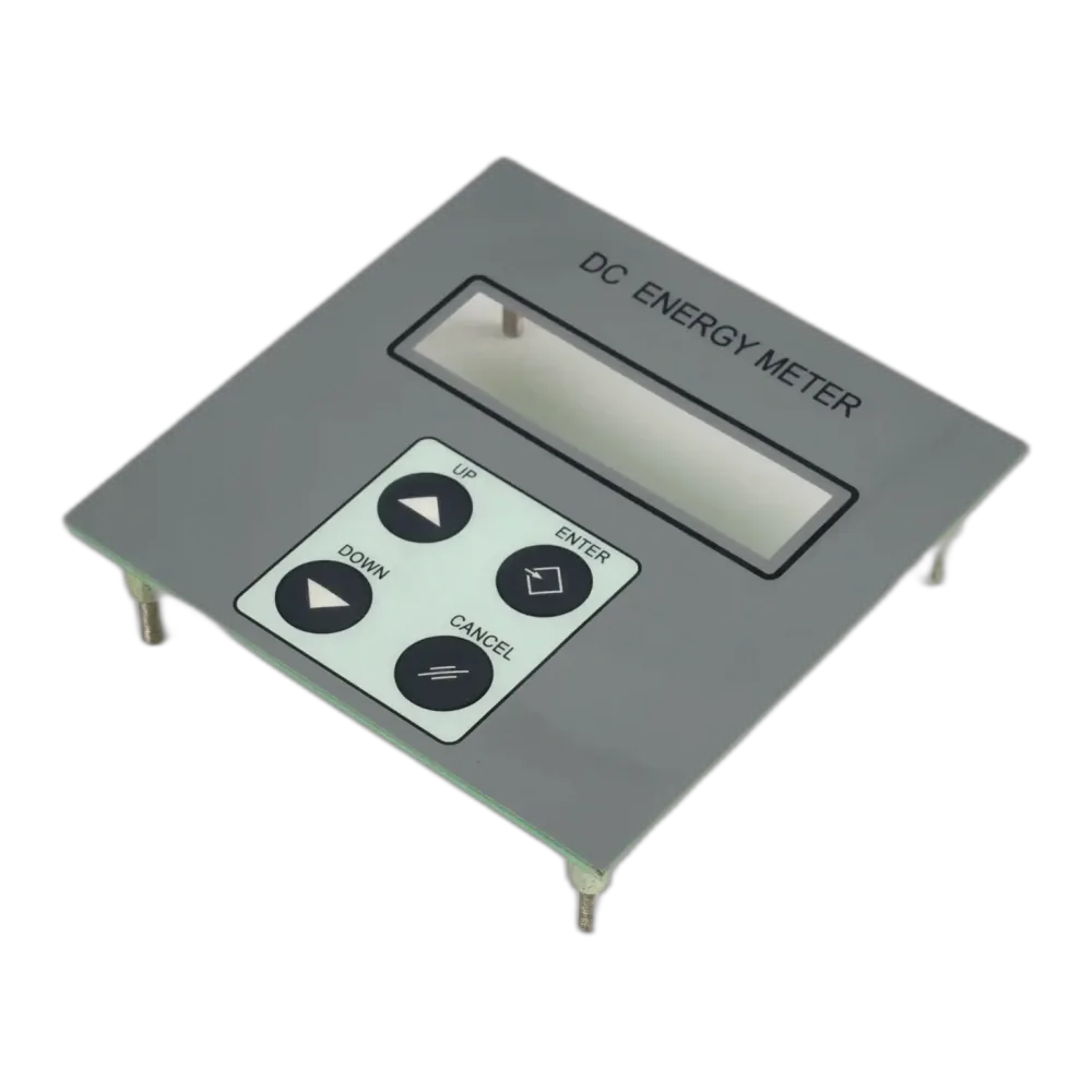
銅オン FR-4 キャリア、銅オンポリイミド フレックス、およびハイブリッド - コントローラーのピン配列に終端され、出荷前にテストされます。
JASPER は、埋め込み MCU、高密度トレース、3D 適合性など、PET 上の銀インクのインターフェースを超えた OEM チーム向けに、PCB ベースの FPC メンブレン スイッチを構築します。
JASPERのスイッチを採用するOEM


シルバーインクの尾がスペースを使い果たす場所に建てられています
キーパッドに電子機器を搭載する必要があるまでは、PET 上の銀インクが主力製品です。
当社は、インターフェースが PET 上に印刷された銀インクの限界を超えている OEM チーム向けに、PCB および FPC メンブレン スイッチを製造しています。キーパッドに MCU を搭載し、バックライト LED を駆動し、12 mm テールに 24 個のトレースを配線し、または湾曲したハウジングの周囲に折り畳む必要がある場合、標準のポリエステル スタックは正しい答えではなくなります。正しい答えは、銅オン FR-4 キャリア、銅オンポリイミド フレックス、またはその両方のハイブリッドです。コントローラのピン配置に終端され、出荷前にテストされます。
Silver-ink-on-PET runs at ~10 μm printed silver, holds 0.30 mm trace and space, and ships at 0.20–0.25 mm total thickness for under a dollar a key in volume. For a 24-key matrix on a flat panel with no embedded electronics, nothing beats it on unit cost — it is still our highest-volume construction within the broader membrane switches family. The PCB-backed and FPC variants exist for the projects where printed traces simply will not do the job.
Quick Answer
PCB または FPC メンブレン スイッチとは何ですか?
PCB または FPC メンブレン スイッチは、標準的なメンブレン キーパッドの銀インクのプリント回路をエッチング銅キャリア、つまりリジッド FR-4 ボード (PCB 裏面)、ポリイミド フレックス回路 (FPC)、または両方を積層したハイブリッドに置き換えます。銅製キャリアは、はんだ付けされた SMT コンポーネント (MCU、LED ドライバー、電流制限抵抗器、2 kV ESD ダイオード) を受け入れ、0.075 mm までのより微細な配線を保持し、湾曲したハウジングの周りに折り畳むことができます。 OEM は、コンポーネント密度、配線密度、または 3D 適合性が、PET 上の銀インクで実現できるレベルを超える場合にこれを選択します。
When standard silver-ink isn’t enough
3 つの制約により、設計が印刷された銀から銅回路に押し出されます。
PET 上の銀インクは、ほとんどのメンブレン キーパッドの主力構造です。 3 つの制約により、設計が主力回路から PCB ベース、FPC、またはカッパーフレックス回路へと押し上げられ、それぞれが経験則ではなく公開された受け入れ基準にマップされます。
JASPER は、銅箔ロットから最終的な 100% 導通テストまでの完全なトレーサビリティを備えた ISO 9001:2015 品質システムに基づいて、PCB と FPC の両方のバリエーションを社内で構築しています。顧客は、同様の作業について Elecflex、Niceone-Tech、および LuphiTech も評価しています。 OEM エンジニアは 5 年間出荷されるビルドについて複数のサプライヤーを比較する必要があるため、これらをリストに挙げます。私たちの仕事が成功する傾向にあるのは、エンジニアリングの対応です。販売テンプレートではなく、RFQ に上級デザイナーを配置します。
| Constraint | Silver-ink limit | Copper circuit answer |
|---|---|---|
| Component density | Printed silver cannot host an MCU, RGB driver, resistors, or TVS diodes | Soldered FR-4 carrier to IPC-A-600 acceptance and J-STD-001 criteria; 2 kV ESD per IEC 61000-4-2 |
| Trace density | 0.30 mm minimum trace / space | Etched copper on polyimide to 0.10 mm — and 0.075 mm with controlled processes |
| 3-D conformability | Single 90° tail fold; not rated for repeated articulation | Polyimide FPC at 6× static / 12× dynamic bend radius, IPC-6013 Class 3 qualified |
14 mm テール上の 5×8 キーパッド マトリクスと共配線された 32 文字のディスプレイ リボンには、印刷されたインクではなく、エッチングされた銅が必要です。曲げ、密度、コンポーネントの数値は、IPC および IEC の受け入れ基準に基づいて記載されています。
Connector and routing review
Construction decides what the keypad can do; routing decides whether it integrates on the first sample.
The connector and routing decide whether the keypad will drop into the customer’s existing harness on the first sample. Tail pitch is locked by the receiving connector: 0.5 mm or 1.0 mm pitch for Molex FFC/FPC, AMP/TE FFC, and Hirose DF series ZIF; 2.54 mm for retrofit into legacy pin-header controllers; bare solder pads for direct PCB integration.
Pin 1 location, tail-entry direction, stiffener position, and ZIF actuator face are all design-time variables. Pinout is fully customer-defined — we route to any sequence including non-monotonic mappings that match existing harnesses. For the broader pool of termination styles we keep in inventory, see our membrane switch connectors reference page.
Why JASPER on a copper build
Etched copper, full SMT, and a pinout report on every batch
The copper carrier is only useful if it is built to a published acceptance standard and terminated to the harness you already ship. These four commitments keep a PCB or FPC build out of the rework loop.
Standards-based acceptance
PCB sections to IPC-A-600 and IPC-2221; flex to IPC-6013 Class 2 or 3; assembly to IPC-A-610; solder to J-STD-001 revision H.
Full SMT capability
0402 and larger passives, SOT-23/SOT-353 actives, LED 0603/0805/1206, QFN MCUs, and ZIF connectors on FR-4. See our LED membrane switches for the backlight side.
ESD & EMI hardening
2 kV TVS diodes per IEC 61000-4-2 on every key input, a perimeter guard ring, and a stitched ground plane on PCB or double-layer FPC.
Traceable, tested, documented
Full traceability from copper foil lot through 100% continuity test, with pin 1 marked and a pinout PDF shipped on every batch.
Where PCB and FPC constructions fit best
Component-dense control panels
Panel-mounted industrial controllers needing an MCU for matrix scan, RGB backlight drivers, and current-limit resistors default to a rigid PCB-backed carrier.
Curved and display-integrated interfaces
FPC wins where the keypad must conform to a curved bezel, co-route with a TFT or OLED display ribbon, or stay below 0.5 mm total stack.
Remote keypad interconnect
Copper flex without the membrane stack, or a hybrid PCB + FPC pigtail, links a remote keypad island to a controller 100 mm away without an extra connector failure point.
RFQ preparation
Send the details that decide construction, tail, and pinout.
Send your panel cutout, target circuit construction, controller pinout, and an indicative quantity. We review materials, layer stack, sealing target, connector family, and lead time before any tooling is cut.
- Panel cutout and enclosure depth budget
- Target construction: PCB-backed, FPC, copper flex, or hybrid
- Controller pinout and connector family (Molex, AMP/TE, Hirose, header)
- Tail pitch, length, exit direction, and stiffener position
- Target sealing level: IP65 or IP67 per IEC 60529
- SMT BOM: MCU, LED drivers, resistors, ESD diodes
製造ベースライン
JASPER supports OEM PCB and FPC membrane switch builds from design review through production in Dongguan, on an ISO 9001:2015 quality system.
PCB carriers use FR-4 rated UL 94 V-0; flex is qualified to IPC-6013 Class 2 or Class 3; assembly follows IPC-A-610 with J-STD-001 revision H soldering. RoHS Directive 2011/65/EU and REACH SVHC compliance, 2 kV ESD protection per IEC 61000-4-2, and full traceability from copper foil lot through final 100% continuity test are available across the build.
見積もりを依頼PCB and FPC membrane switch questions
When should I use a PCB-backed membrane switch vs an FPC one?
Pick PCB-backed when the keypad must carry SMT components — an MCU, LED drivers, current-limit resistors, 2 kV ESD diodes per IEC 61000-4-2 — survive panel-mount rigidity, or run higher current to backlight LEDs. Pick FPC when the keypad has to fold around a curved housing, share a tail with a display ribbon, hit a total thickness below 0.5 mm, or follow a non-flat panel. PCB-backed adds rigidity and full SMT capability per J-STD-001. FPC adds 3-D conformability qualified to IPC-6013 Class 2 or Class 3. Both replace silver-ink-on-PET when conductivity, trace density, or component-density requirements exceed printed traces. JASPER builds both constructions on the same factory floor and will recommend by application during the RFQ review.
Can a PCB membrane switch include SMT components?
Yes. The FR-4 carrier in a PCB-backed build accepts standard SMT process: 0402 and larger passives, SOT-23 and SOT-353 actives, LED packages in 0603 / 0805 / 1206, QFN-packaged microcontrollers, and ZIF connectors. We assemble per IPC-A-610 acceptance and solder per J-STD-001 revision H. Common builds carry an MCU for matrix scanning, RGB LED drivers, current-limit resistors, and 2 kV ESD diodes on every key input. SMT on FPC is restricted to qualified flex parts — typically 0603 and larger — built on stiffened pads with a reduced reflow profile that respects polyimide thermal limits. Component lists, BOM, and assembly drawings are reviewed at the sample stage before any tooling is cut. For the backlight side of these integrated builds, see our LED membrane switches catalog.
What’s the connector and pinout flexibility on a PCB or FPC membrane switch?
Both PCB-backed and FPC constructions accept any pinout the customer specifies — sequential, scrambled to match a legacy harness, or with intentional pin gaps for keyed alignment. Tail pitch is set by the receiving connector: 0.5 mm or 1.0 mm for Molex, AMP/TE, and Hirose ZIF/FFC families; 2.54 mm for retrofit into legacy pin headers; bare-pad solder for direct PCB-to-PCB integration. Tail length, tail width, stiffener position, and exit direction are all open at design time. JASPER routes the tail to the customer’s controller pinout — no fixed factory mapping is required. We mark pin 1 on every drawing release and ship a pinout PDF with every batch.
Continue the membrane switch construction review
Membrane switches
Return to the membrane switch family hub to compare keypad structures, circuits, overlays, and sealing choices.
Review membrane switches →LED membrane switches
Plan backlight driver placement, RGB LED packages, and the integrated PCB carriers that power them.
Review LED switches →Membrane switch design
See how we review stack-up, circuit construction, tail routing, sealing, and grounding before tooling.
Review design support →Prototyping
The rapid-build workflow behind five fully terminated samples in 10 working days for engineering evaluation.
Review prototyping →Get a PCB or FPC sample built to your pinout
Send us your panel cutout, target circuit construction, controller pinout, and an indicative quantity, and we will build five fully terminated samples to that spec within 10 working days for engineering evaluation. Every sample run includes 100% continuity test on every key, a pinout verification report, and a connector mating-cycle check against your named ZIF or pin-header part number. Most projects close the spec-to-sample loop in two iterations. メール your drawing package or RFQ and a JASPER engineer responds the same business day.
Start RFQ ReviewWant the rapid-build workflow first? See how we run prototyping for OEM membrane switch projects.