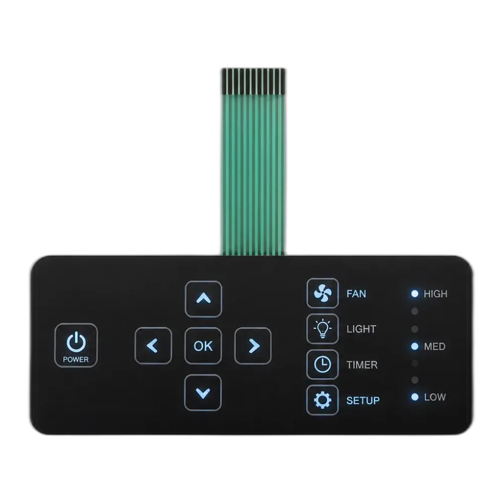
電源・ステータス・アラーム・モード・デッドフロント
LED メンブレンスイッチ with Indicators and Backlit Icons
表面実装 LED がプリント回路層に組み込まれているため、パネルが機械の動作をオペレータに知らせます。
JASPER は、0.5 ~ 1.2 mm メンブレン スタック内に 0603、0805、および 1206 SMT LED を統合し、OEM コントロール パネルの電源、ステータス、アラーム、モード、およびデッドフロント フィードバックを実現します。
JASPERのスイッチを採用するOEM


購入者がライトフィードバックを選択する理由
私たちのパネル上の LED は単なる照明ではありません。それぞれに役割があります。
Lighting up a panel is the easy part. Making the panel say something is the harder one, and the reason every LED on a JASPER stack carries an assigned semantic role — power, status, alarm, mode, or a dead-front icon. Each layer of the build — overlay, ink, spacer, circuit, adhesive — gets pulled in to support whichever role the design needs.
An LED membrane switch is the lit member of the membrane switches family. We have integrated indicators into stacks for medical, instrumentation, industrial-automation, and appliance OEM programs, and the same SMT LEDs sit beside metal-dome tactile keys when a button needs both a click and a coloured ready-light. For whole-panel illumination rather than discrete indicators, our backlit membrane switches use a side-fire light guide instead; for a side-by-side of the lighting technologies, see our membrane switch backlighting options guide comparing LED, EL, and fibre-optic backlighting.
Quick Answer
LEDメンブレンスイッチとは何ですか?
JASPER LED メンブレン スイッチは、プリント回路層の内側に表面実装 LED (0603、0805、または 1206) を配置します。その結果、機能がオフのときに消える死角アイコンを含む、何が起こっているか (電源、ステータス、アラーム、モード) をオペレーターに知らせる 1.2 mm 以下のスタックが得られます。配置、不透明マスキング、ウィンドウ素材、Vf ビニング、スタックアップ、および IEC 60529 シーリングという 6 つの選択項目を組み合わせて、パネルがきれいに読み取れるかどうかを決定します。 6 つの無関係な仕様ではありません。
フィードバックのために構築
5 つのインジケーターの役割と、ビルドのすべてのレイヤーがそれらをサポートします。
まず電源インジケーターを見てみましょう。515 nm の 0603 緑色 LED、またはパネル パレットで必要な場合は 470 nm の青色エミッターが、軸から 45 度 (技術者がベンチトップに寄りかかる角度) でドットが読み取れるようなサイズの 3 mm の円形窓の後ろに配置されています。
Status is where it gets interesting. A multi-colour RGB LED gives one physical button three readings — ready, busy, fault — and the driver runs PWM at ≥200 Hz so peripheral vision stops noticing the chop. We bin reels by forward voltage within ±0.05 V before placement; skip that and a row of “ready” lights ends up looking like slightly different colours, which trains operators to ignore the row.
Alarm uses a red 630 nm LED blinking at 1–2 Hz off a hardware driver, not a firmware loop — a firmware loop dies the moment the firmware does, exactly when you need the alarm. Mode is the quiet one: an amber 590 nm LED latched on while the operator is in jog, calibration, or programming, so the panel shows what the firmware thinks the machine is doing.
Reading the lit panel
How we keep indicators legible once the LEDs switch on
An LED only earns its place when the operator can read it instantly. These four controls keep status, alarm, and mode unambiguous on a JASPER LED membrane keypad.
Uniform brightness
We bin every reel by forward voltage within ±0.05 V before placement, so a row of “ready” lights reads as one colour rather than a shopping list of near-matches.
Dead-front masking
Fault, overload, and water-low glyphs print in black opaque ink at OD ≥1.5 behind tinted polycarbonate, invisible until a 4000 K white emitter glows them through.
Flicker-free dimming
Status and mode LEDs dim under PWM at ≥200 Hz so peripheral vision never catches the chop, while alarm blink runs off a hardware driver independent of firmware.
No cross-key bleed
A 1.5–2 mm dark border and UL 969-verified opaque ink isolate each window, a layout discipline we carry across every membrane keypads project that runs LEDs.
Where LED indicator panels fit best
Medical and instrumentation
Status, alarm, and dead-front mode icons on bedside monitors and analyzers, often on Class 3 polyimide circuits with conformal coating.
Industrial automation
Ready / busy / fault status next to tactile keys at 1.5–4 N, sealed to IP65 or IP67 for cabinet and machine-side HMIs.
Appliance and consumer
Power and mode indicators behind matte PC windows where a single dot must stay crisp under bright kitchen and ceiling lighting.
RFQ preparation
Send the panel details that decide where the LED feedback lands.
Send your panel artwork (AI, PDF, or DXF) and a one-line note on where the LED feedback needs to land — power, status, alarm, mode, dead-front, or all of the above. We review materials, layer stack, masking, sealing target, and lead time before tooling.
- Panel artwork in AI, PDF, or DXF
- LED roles needed: power, status, alarm, mode, dead-front
- Window material: PC 0.25 mm or PET 0.175 mm
- Target sealing level: IP65 or IP67 per IEC 60529
- Circuit class: IPC-A-600 Class 2 or Class 3
- Operating temperature and tactile-key requirement
製造ベースライン
JASPER supports OEM LED membrane switch builds from design review through production in Dongguan.
Our default circuit layer ships at IPC-A-600 Class 2, with Class 3 available on request for medical and aerospace builds. RoHS and REACH material options are available, and every panel leaves the line with a photometric witness coupon recording brightness uniformity and dominant wavelength, with ISO-certified process control across a 5,000 m² factory and 2,500 m² cleanroom production area.
見積もりを依頼LED membrane switch questions
What is a dead-front LED membrane switch, and how does the icon disappear when off?
Dead-front hides a graphic until its LED activates. The icon is printed in black opaque ink (OD ≥1.5) on the back of a tinted PC or PET overlay, with the LED mounted on the circuit layer directly beneath. LED off — the masked area absorbs ambient light and the panel reads as a single dark surface. LED on — a 4000 K white emitter behind the icon makes it glow through the tinted window. We reach for it on fault, overload, and safety-mode icons where visual clutter at rest is unwanted.
Can LED indicators coexist with tactile (domed) keys in the same membrane switch?
Yes — that is the most common configuration we build. Tactile feedback comes from SS 304 0.075 mm metal domes seated in the spacer/circuit layers at 1.5–4 N actuation. The LEDs (0603 to 1206 SMT) sit on the same printed circuit next to the domes, not under them, so the dome’s snap action is unaffected. Total stackup stays at 0.5–1.2 mm. A typical layout pairs a tactile key with a status LED at its corner — one button gives both clicky feedback and a coloured ready-light. Indicator LEDs and clicky tactile keys share one assembly, not two stacked subassemblies — important if the enclosure already eats most of the height budget.
What stops LED light from leaking between keys on a membrane keypad?
Three controls, working together. First, an opaque black ink ring around every LED window with optical density ≥1.5 — single layer for indicator panels, layered black-plus-white blockout for dead-front graphics. Second, a 1.5–2 mm dark border between window edge and the next key, sized against the LED’s viewing angle. Third, a low-scatter adhesive plus a perimeter gasket that isolates each lit zone mechanically. We bench-verify with a photometric witness coupon on every production lot.
Continue the membrane switch design review
Review light guide, LED color, masking, windows, and light leakage details in the PDF:
backlighting-review-checklistBacklit membrane switches
Compare side-fire light guides and whole-panel illumination for projects that need a lit zone, not discrete indicators.
Review backlit switches →Membrane switches
Return to the membrane switch family hub to compare keypad structures, circuits, overlays, and sealing choices.
Review membrane switches →PCB and FPC membrane switches
See the circuit-substrate companion — silver-ink PET, polyimide FPC, and rigid PCB options behind the LEDs.
Review circuit options →Membrane switch design
See how we review stack-up, masking, LED placement, sealing, and feedback before tooling.
Review design support →Get an LED membrane panel quoted by our engineers
Send your panel artwork (AI, PDF, or DXF) and a one-line note on where the feedback needs to land. We come back inside 24 hours with a layer-stack recommendation, a BOM, and a quote — using the same IPC-A-600, IEC 60529, and UL 969 baselines that supply our ISO-certified production in Dongguan.
Start RFQ ReviewNeed whole-panel light instead of indicators? See our backlit membrane switches for area illumination.