Set a pressure sensor mat threshold from measured empty-state and occupied-state data in the final mechanical assembly, not from one bench reading. If the signal increases with load, a useful starting condition is N_high < T_off < T_on < O_low, where N_high is the highest credible empty-seat signal and O_low is the lowest credible occupied-seat signal. Separate switch-on and switch-off thresholds create hysteresis. Time qualification, often called debounce, prevents brief disturbances from changing the state.
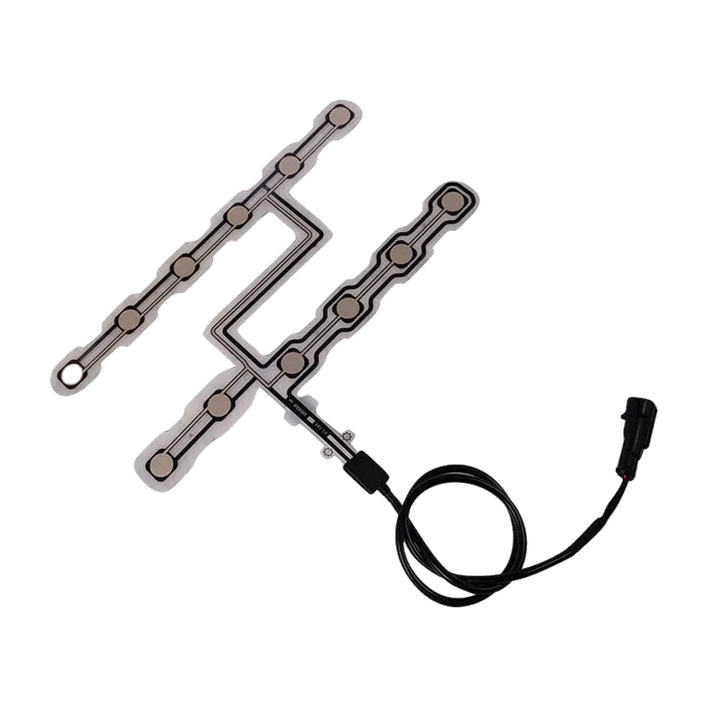
The threshold is only as good as the load path that produces it. For a custom pressure sensor mat, the mat outline, sensing zone, foam, upholstery preload, installation position, circuit behavior, cable, and connector should be reviewed as one system. If the empty and occupied distributions overlap, changing one software number will not make the system reliable.
Updated: July 15, 2026
- Threshold Terms at a Glance
- First Identify the Mat Output Type
- What Is the Correct Relationship Between the Thresholds?
- What if the empty and occupied data overlap?
- A Normalized Threshold and Hysteresis Example
- Hysteresis and Debounce Solve Different Problems
- Hysteresis controls signal amplitude
- Debounce controls time
- How Does Preload Change the Empty Baseline?
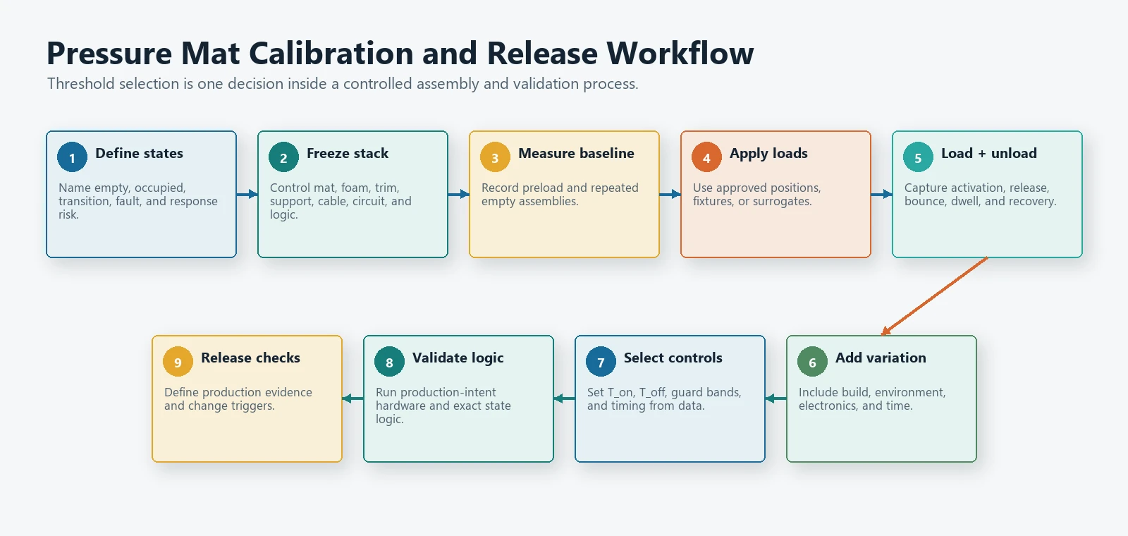
- A Practical Calibration Workflow
- Step 1: Define the states and the decision risk
- Step 2: Freeze the representative stack
- Step 3: Measure the empty baseline and preload
- Step 4: Apply the required occupied conditions
- Step 5: Test loading and unloading
- Step 6: Add environmental and assembly variation
- Step 7: Select T_on, T_off, and time qualification
- Step 8: Validate the state machine
- Step 9: Define production and change-control checks
- Recommended Data Collection Matrix
- How to Write Acceptance Criteria
- Common Threshold-Setting Mistakes
- Using one sample and one load
- Calibrating the bare mat
- Using one threshold for both directions
- Treating debounce as a cure for overlapping data
- Ignoring preload after assembly changes
- Reporting only average values
- Confusing occupied state with measured force
- What Should an OEM Send for Threshold Review?
- Review a Pressure Mat Threshold Plan
- Related JASPER Resources
Threshold Terms at a Glance
| Term | Engineering meaning |
|---|---|
| Baseline | The measured output with the assembled seat or product in its defined no-load state. |
| Preload | Force already applied by foam, upholstery, adhesive, housing compression, assembly tension, or another mechanical source before the target load is added. |
Switch-on threshold, T_on |
The signal or mechanical condition that must be exceeded before the state changes to occupied or active. |
Switch-off threshold, T_off |
The lower signal or release condition that must be crossed before the state returns to empty or inactive. |
| Hysteresis | The separation between the switch-on and switch-off boundaries. |
| Debounce or time qualification | A requirement that the input remain valid for a defined time before the state changes. |
| Guard band | Deliberate separation between observed data and the decision threshold to account for uncertainty and variation. |
| Chatter | Repeated state changes when the signal or contact moves around one decision boundary. |
First Identify the Mat Output Type
The phrase “pressure sensor mat” can describe several different electrical behaviors. Threshold development starts by identifying which one the project actually uses.
| Mat type | Raw output | Where the threshold exists | Main calibration task |
|---|---|---|---|
| Contact-type membrane mat | Open/closed contact or continuity change | Primarily in the mechanical actuation and release loads; electronics detect a stable state | Confirm actuation, release, bounce, preload, and repeatability in the final stack |
| Resistive or analog mat | Resistance, voltage, conductance, or ADC count changes with load | In the analog signal chain and control logic | Map empty and loaded distributions, then select thresholds and filtering |
| Multi-zone mat | Separate contact or analog channels | Per zone and sometimes in combined decision logic | Validate each zone, cross-zone loading, and the final state rule |
| Conditioned sensor module | Digital or processed analog output | Inside the module and system controller | Confirm interface specification, timing, fault states, and system acceptance |
A contact-type mat is not a low-resolution analog sensor. Its useful output may simply be a stable contact closure. In that case, the “trigger threshold” is largely a mechanical design result: spacer geometry, contact area, cushion load path, and assembly preload determine when the contact closes and opens.
An analog mat has a continuously changing signal, but that does not mean every ADC count is a reliable measurement. The signal still needs a decision rule based on the complete assembly.
For the resistance-based sensing mechanism behind some analog constructions, see how a force sensing resistor works. Contact-type mats still require a separate actuation, release, bounce, and preload review.
What Is the Correct Relationship Between the Thresholds?
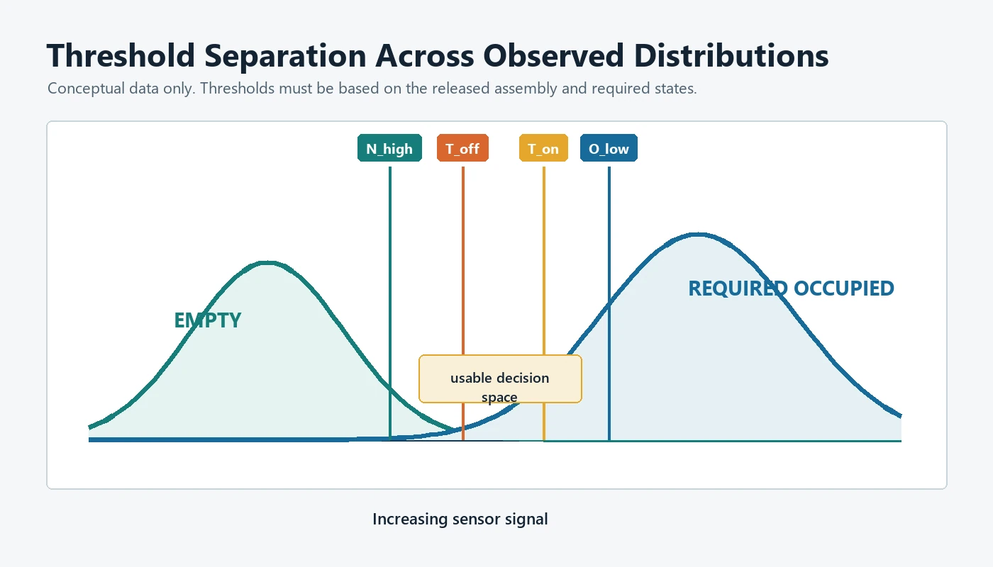
Assume the signal rises as load increases. Define:
N_high: highest credible empty-state signal;O_low: lowest credible required occupied-state signal;T_on: threshold for changing from empty to occupied; andT_off: threshold for changing from occupied to empty.
For a clean separation:
N_high < T_off < T_on < O_low
The rule means:
- A worst-case empty seat remains below the release threshold.
- A required occupied condition remains above the activation threshold.
- The gap between
T_offandT_onprevents one noisy boundary from controlling both state changes.
If the sensor signal falls as load increases, reverse the inequalities and state logic.
What if the empty and occupied data overlap?
If O_low is equal to or below N_high, no single threshold can separate every observed empty and occupied case. More filtering may hide some transitions, but it does not create missing physical separation.
The engineering options are then to:
- move or resize the sensing zone;
- change the mat structure or circuit;
- control preload and cushion tolerances;
- improve the load spreader or mechanical interface;
- use more than one sensing zone;
- add another independent input;
- narrow the required operating conditions; or
- revise the classification requirement.
This is an important stop condition. A threshold should not be approved until the measured distributions support the required decision.
A Normalized Threshold and Hysteresis Example
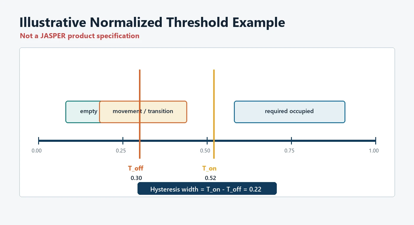
The following example uses a normalized signal from 0.00 to 1.00. It is an explanatory model, not a JASPER product specification and not a recommended vehicle threshold.
| Test group | Observed normalized range | Interpretation |
|---|---|---|
| Empty assembled condition | 0.08 to 0.22 |
Includes normal preload and sample variation |
| Movement or transition cases | 0.18 to 0.44 |
Includes brief load shifts that should not activate the occupied state |
| Required occupied condition | 0.58 to 0.91 |
Lowest required occupied result begins at 0.58 |
One candidate decision pair could be:
T_on  = 0.52
T_off = 0.30
Hysteresis width = T_on - T_off = 0.22
The candidate T_on is above the observed transition range and below the lowest required occupied result. The candidate T_off is above the highest empty result but well below T_on. An occupied state is therefore retained while the signal stays above 0.30; a lower signal must satisfy the approved release-time qualification before the state changes.
Normalized signal, rising with load

0.00      0.22      0.30          0.44      0.52      0.58          1.00
 |----------|---------|--------------|---------|---------|--------------|
    empty       T_off     movement        T_on     required occupied
This example is not complete until it includes uncertainty, additional seats or products, environmental conditions, load positions, loading and unloading, dwell time, and repeated cycles.
Hysteresis and Debounce Solve Different Problems
Hysteresis and debounce are often discussed together, but they are not the same control.
Hysteresis controls signal amplitude
Hysteresis uses two decision levels. The input must cross T_on to activate, but it must later cross T_off to release. The system holds its current state while the signal remains between the thresholds.
A comparator can implement hysteresis in hardware: positive feedback creates different rising and falling trip points so a noisy or slowly moving input does not repeatedly toggle at one threshold.
Debounce controls time
Debounce requires a candidate state to remain valid for a defined interval or number of samples. It rejects a brief contact bounce, vibration pulse, occupant movement, connector disturbance, or ADC spike.
Use the controls together:
If current state is EMPTY:
    change to OCCUPIED only when signal >= T_on
    continuously for the approved activation time

If current state is OCCUPIED:
    change to EMPTY only when signal <= T_off
    continuously for the approved release time

Otherwise:
    hold the current state
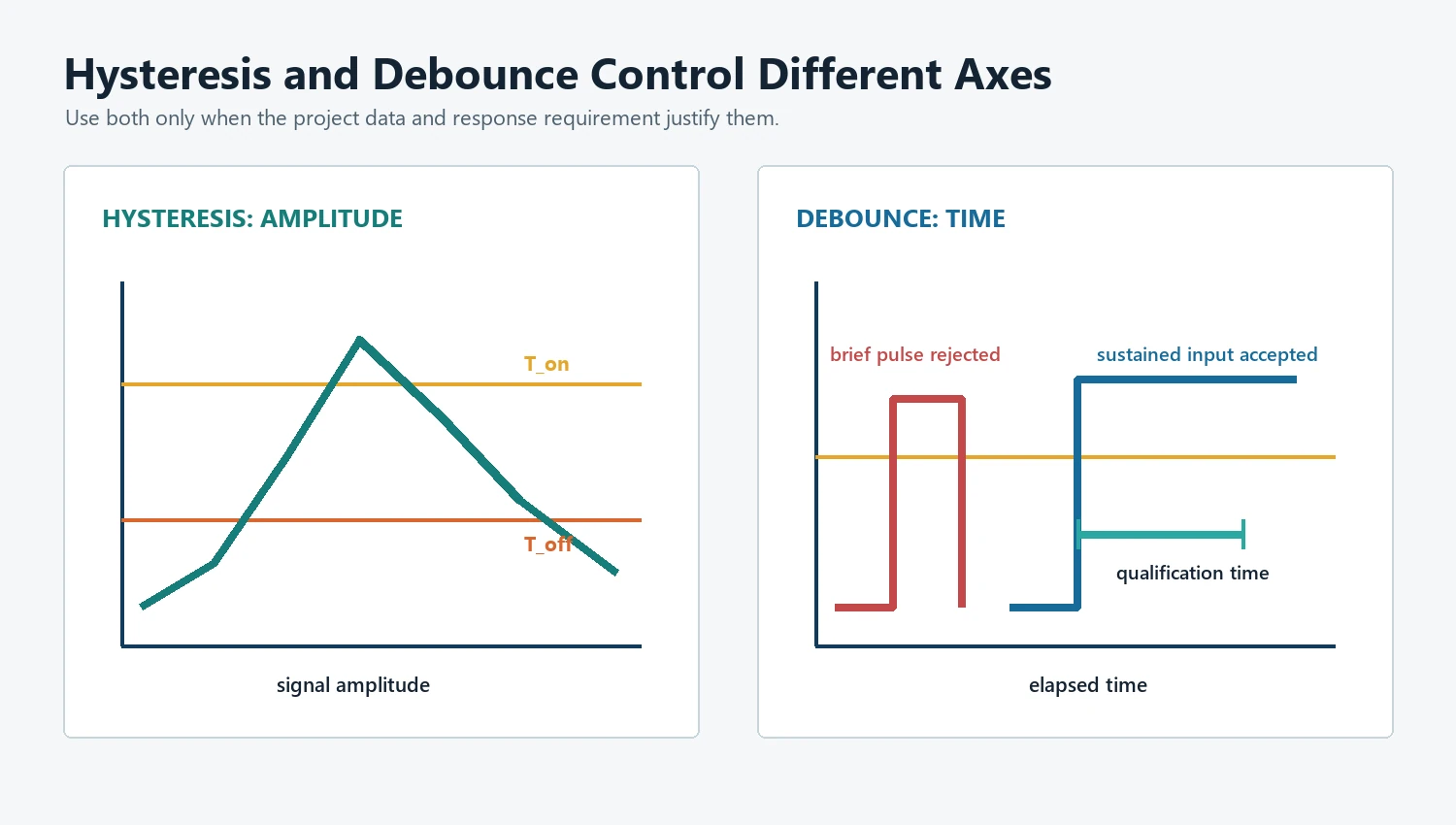
The activation and release times do not have to be equal. They should come from the system response requirement and test data, not from a copied software constant.
Too little debounce allows chatter. Too much debounce can delay a required state change or hide an intermittent fault. The timing decision belongs in the system requirement and validation plan.
How Does Preload Change the Empty Baseline?
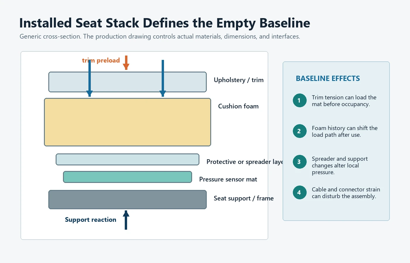
An empty installed mat is rarely mechanically unloaded. Seat trim, cushion foam, protective layers, adhesives, clips, wires, assembly pressure, and the seat frame can create preload.
Preload matters in three ways:
- Baseline shift: The empty output may start above the bare-sensor value.
- Reduced margin: A higher empty baseline leaves less separation before
T_on. - Different release behavior: Foam and trim can continue applying load after the main occupant force is removed.
Measure the empty baseline after full assembly. Repeat it after the cushion has been loaded and released, after thermal conditioning where required, and across representative build tolerances. A threshold based only on a new, untrimmed cushion can fail after the production stack is installed.
For a contact mat, preload can partially close or bias the contact area. For an analog mat, it can consume part of the signal range. Both cases require mechanical review before changing the controller threshold.
A Practical Calibration Workflow
Step 1: Define the states and the decision risk
Write the actual requirement:
- Which conditions count as empty?
- Which conditions must count as occupied?
- Are transitional or ambiguous cases allowed to hold the previous state?
- Which error is more critical: false occupied or missed occupied?
- What activation and release response times are allowed?
Do not begin with an arbitrary target force. Begin with the system decision.
Step 2: Freeze the representative stack
Document:
- mat revision and sensing-zone geometry;
- installation position;
- cushion and foam;
- upholstery and trim tension;
- adhesive or attachment;
- load spreader or cover layer;
- cable route and connector;
- measurement circuit; and
- controller sampling and filtering.
If any of these change, decide whether recalibration is required.
Step 3: Measure the empty baseline and preload
Collect data from multiple assemblies and repeated installations. Include initial empty data, empty data after loading, and the expected product orientations or seat adjustments.
Record the distribution, not only the average. The highest credible empty value is more relevant to T_off than the mean empty value.
Step 4: Apply the required occupied conditions
Use customer-defined loads, positions, fixtures, or approved surrogates that represent the target application. Measure the lowest credible occupied result across the required conditions.
For a multi-zone mat, record each zone separately before evaluating the combined decision.
Step 5: Test loading and unloading
Approach each condition from both directions. The activation point and release point may differ because of the mat structure, foam behavior, friction, or control logic.
Record:
- activation signal or mechanical load;
- release signal or mechanical load;
- transition time;
- bounce or oscillation;
- dwell behavior; and
- recovery after unloading.
Step 6: Add environmental and assembly variation
The validation matrix should reflect the product risk. Possible factors include:
- temperature;
- humidity or moisture exposure;
- cushion conditioning;
- foam and upholstery tolerance;
- sensor and spacer variation;
- adhesive thickness;
- mounting position;
- supply and reference variation;
- connector and harness resistance;
- load position;
- repeated loading; and
- time under load.
NIST measurement-process guidance separates short-term repeatability, longer-term variability, calibration effects, bias, and uncertainty. That framework is useful here because a threshold must survive more than repeated measurements on one sample in one fixture.
Step 7: Select T_on, T_off, and time qualification
Choose thresholds only after plotting the empty, transition, and occupied distributions. Add a guard band rather than placing a threshold directly on the worst observed point.
Then select activation and release times from real transition data and the product response requirement. Document the rule, signal direction, filter, sample rate, timing, and fault behavior.
Step 8: Validate the state machine
Run the exact controller logic against recorded data and production-representative hardware. Check:
- false activation;
- missed activation;
- release failure;
- repeated chatter;
- excessive delay;
- zone disagreement;
- open or short fault handling; and
- startup and power-cycle behavior.
Step 9: Define production and change-control checks
Not every production unit needs the full development test matrix. The production check should verify the critical characteristics that protect the approved threshold margin.
JASPER’s testing and quality-control process can be aligned with project-specific drawings and acceptance requirements, but the seat-system owner must define the final functional criteria and approve the validation method.
Recommended Data Collection Matrix
| Factor | Minimum question to answer | Why it affects the threshold |
|---|---|---|
| Empty assembly | What is the highest empty signal after complete installation? | Defines the lower classification boundary |
| Required occupied cases | What is the lowest occupied signal that must be recognized? | Defines the upper classification boundary |
| Load position | Does the result change at the center, edge, or between zones? | Reveals sensing-area and load-path gaps |
| Loading direction | Are activation and release points different? | Quantifies mechanical and electrical hysteresis |
| Dwell | Does the signal move while the load remains applied? | Tests stability and delayed state changes |
| Repetition | Does the same assembly return to the same range? | Measures repeatability |
| Assembly samples | Do different mats and cushions stay within the same bands? | Measures part and build variation |
| Environment | Do temperature, humidity, or conditioning shift the baseline? | Tests threshold margin outside the laboratory |
| Electronics | Do supply, reference, ADC, resistor, and connector changes matter? | Protects the decision from circuit variation |
| Faults | What happens for open circuit, short circuit, or disconnected zone? | Separates sensor state from hardware fault |
How to Write Acceptance Criteria
An acceptance criterion should identify the input condition, expected state, timing, repetition, environment, and allowed failures.
Use a structure such as:
Given:
    approved seat or product assembly revision
    defined environmental condition
    defined empty or occupied test condition

When:
    the condition is applied for the specified dwell

Then:
    the controller shall reach and hold the required state
    within the approved response time
    without prohibited chatter or fault indication

Repeat:
    across the specified samples, positions, cycles, and environments
The numbers belong in the controlled customer specification or approved test plan. Do not hide them only in firmware comments or an informal spreadsheet.
For automotive applications, a component-level pressure-mat result is not the final vehicle decision. The OEM or seat-system integrator remains responsible for system logic, risk analysis, compliance, diagnostic behavior, and vehicle-level validation.
Common Threshold-Setting Mistakes
Using one sample and one load
One clean bench trace shows feasibility, not production margin. Use multiple assemblies, repeated cycles, and relevant conditions.
Calibrating the bare mat
The cushion, trim, mounting, and housing create the real load path. Bare-mat values cannot represent the finished product without evidence.
Using one threshold for both directions
A single boundary makes a slowly changing or noisy signal more likely to chatter. Separate activation and release thresholds where the system architecture allows it.
Treating debounce as a cure for overlapping data
Timing can reject brief transitions. It cannot reliably separate two steady conditions that produce the same signal range.
Ignoring preload after assembly changes
A new foam supplier, trim process, adhesive, mat position, or cushion revision can shift the empty baseline. Change control should identify which modifications require revalidation.
Reporting only average values
Thresholds fail at distribution edges. Record minima, maxima, spread, outliers, sample identity, and test conditions.
Confusing occupied state with measured force
A mat can make a reliable binary decision without reporting an accurate force. Do not add a force value unless the sensor, mechanics, electronics, and calibration support it.
What Should an OEM Send for Threshold Review?
Provide:
- Seat or product drawing and installation position.
- Mat outline, sensing zones, cable route, connector, and circuit behavior.
- Defined empty, occupied, and transitional conditions.
- Expected load range, contact area, position, dwell, and loading rate.
- Foam, upholstery, cover, adhesive, and support-stack information.
- Signal direction, supply, interface circuit, ADC or digital input, and sample rate.
- Proposed
T_on,T_off, debounce, filtering, and fault-state logic, if available. - Environmental, lifecycle, and assembly-tolerance requirements.
- Prototype quantity, sample schedule, and acceptance-test plan.
- Production volume and required inspection records.
If the threshold bands are not yet known, send the mechanical stack and decision requirement first. The prototype stage should generate the data needed to set them.
Multi-zone array design: resolve array topology and scan behavior before thresholds.
Frequently Asked Questions
What is hysteresis in a pressure sensor mat?
Hysteresis is the difference between the condition that activates the occupied state and the condition that releases it. It can come from the mat mechanics, foam, upholstery, analog signal, comparator, or controller logic. Separate T_on and T_off thresholds prevent one noisy boundary from controlling both transitions.
Is hysteresis the same as debounce?
No. Hysteresis is an amplitude or load gap between activation and release. Debounce is a time requirement that rejects brief state changes. Many systems need both.
Can every seat use the same trigger threshold?
Not without validation. Cushion geometry, foam, trim tension, sensing-zone position, mat structure, electronics, and assembly tolerance can change the empty and occupied distributions.
How much guard band is enough?
There is no universal percentage. The guard band should account for measurement uncertainty, sample variation, environment, aging or conditioning, assembly tolerance, and the consequence of a wrong decision.
What if the mat chatters near the threshold?
First determine whether the cause is signal noise, contact bounce, mechanical movement, overlapping state distributions, connector disturbance, or inadequate hysteresis. Add filtering or debounce only after the physical cause and required response time are understood.
Should calibration use force or pressure?
Use the quantity the mechanical requirement and fixture can control. Force, contact area, and pressure are related but not interchangeable. Record the contact geometry and load path so the test can be reproduced.
Related validation: See collecting validation evidence before threshold release.
Review a Pressure Mat Threshold Plan
Send the seat drawing, mat and circuit revision, empty and occupied definitions, load positions, signal data, proposed thresholds, debounce logic, connector, environment, and sample plan through the JASPER request-for-quote form. The review should confirm whether the available threshold margin is sufficient or whether the sensing zone, mechanical stack, mat structure, or validation plan needs to change.
Related JASPER Resources
- JASPER Electronics, “Seat Occupancy Sensor Mat”, current product scope and engineering inputs.
Ready to Start Your Project?
Tell us about your membrane switch, keypad, or graphic overlay requirements. Our engineering team will review your specifications and provide a detailed quote.