
LED · LGF · EL · dead-front
Interruptores de membrana retroiluminados with LED Options
Personalizado illuminated membrane keypads engineered so legends, icons, and indicators stay readable in low-light medical, marine, and industrial environments.
JASPER fabrica ensamblajes backlit membrane switch considerando mascara de luz, espesor del stack, rail de alimentacion y alineacion de arte antes de iniciar el utillaje.
OEMs que integran nuestros switches en sus equipos


Por que las interfaces de baja luz necesitan iluminacion controlada
An operating room at 2 a.m., a ship bridge under red-light protocol, and a packaging line on a 12-hour night shift all need readable controls. El problema no es solo el brillo. Un brillo blanco intenso puede afectar la vision adaptada a la noche, mientras que una fuga de luz a traves de un overlay opaco puede lavar displays cercanos.
JASPER disena backlit membrane switches para que la iluminacion aparezca en leyendas, iconos, ventanas e indicadores previstos, mientras las capas de mascara bloquean brillos no deseados.
Respuesta rapida
Que es un backlit membrane switch?
Un backlit membrane switch usa iluminacion puntual LED, light guide film (LGF), panel electroluminiscente (EL), mascara dead-front o ventana transparente para hacer visibles teclas y leyendas en baja luz. LED and LGF are the most common choices for OEM medical, marine, and industrial equipment because they provide 50,000+ hour lifespans at 3.3 V or 5 V DC without an inverter.
Controlled low-light readability
Light should appear where it is needed and stay blocked where it is not.
JASPER manufactures in a 2,500 m² ISO-class cleanroom in Dongguan. Every backlit assembly ships RoHS- and REACH-compliant. UL-recognized materials are available on request for North American medical and industrial certification programs.
We review stack thickness, masking artwork, light source position, and power supply during DFM so the finished interface stays readable after installation.
Manufacturing baseline
Standard sample lead time is 15 working days from approved artwork. Prototype quantities can start as low as 10 pieces, then scale through the same Dongguan cleanroom workflow.
A backlit stack is a switching interface plus a light-control system.
Full assembly thickness with graphic overlay, spacer, circuit, backer, and backlight typically lands between 1.5 mm and 3.5 mm depending on method and whether a rigid aluminum or FR4 backer is specified.
Light leakage is controlled with a dedicated 0.05–0.1 mm black polyester masking layer. We cut apertures with a CO₂ laser to ±0.1 mm tolerance and verify dead-front opacity at ≥95% optical density before lamination.
LED and LGF assemblies run on 3.3 V or 5 V DC, the same rails already present in many embedded systems. EL panels require a 100–200 V AC inverter at 400–1,000 Hz, which adds cost, EMI risk, and a component that can fail independently of the switch itself. For battery-powered devices, LED or LGF is usually the safer design choice.
Dead-front and selective-backlit projects need two artwork files: one for the visible overlay and one for the masking layer. We run a DFM check before cutting film and can provide a pre-production light-box photo for customer approval before full production begins.
Consideraciones de ingenieria
Four details decide whether the backlight works in the field.
Brightness alone does not make a membrane switch usable. Stack thickness, masking, power supply, and artwork alignment are what keep the interface readable after installation.
Stack thickness
Non-backlit switches are often 0.8–1.2 mm. LED point-lighting brings the assembly to 1.2–2.0 mm; full backlit assemblies usually finish at 1.5–3.5 mm.
Light leakage
A dedicated masking film and ≥95% dead-front optical density prevent halo effects and uncontrolled glow around legends.
Power supply
LED and LGF assemblies run on 3.3 V or 5 V DC. A typical 10-key LGF panel draws 20–80 mA at 5 V.
Artwork alignment
Dead-front and selective-backlit projects need separate overlay and masking artwork. A 0.2 mm mismatch can create a visible halo.
Retroiluminacion is most valuable when operators cannot stop to search for a key.
Medical and surgical equipment
OR control panels, anesthesia workstations, and patient monitors benefit from dead-front or LGF backlighting. Antibacterial polyester overlays tested to ISO 22196 are available for chemically disinfected surfaces.
Marine and naval systems
Ship bridge consoles can require SOLAS night-lighting discipline. Red-backlit LGF assemblies with 625–630 nm LEDs help protect scotopic vision on commercial vessels and naval platforms.
Industrial night-shift operations
CNC panels, packaging line HMIs, and process controls use backlighting to reduce eye strain without glare. LGF with matte overlay gloss at 60° ≤10 GU is the standard solution.
RFQ preparation
Send the light-control details before tooling starts.
We work with OEM design engineers from initial DFM review through production. Send the details below and we will return a DFM report and sample quote within 3 business days.
- Panel dimensions and enclosure depth budget
- Key count, icon areas, and display windows
- Preferred method: LED, LGF, EL, dead-front, or transparent window
- Power rail: 3.3 V, 5 V, or EL inverter constraints
- Operating environment: OR, bridge, night-shift line, or outdoor equipment
- Artwork files for overlay and masking layers
Sample and compliance baseline
Standard sample lead time: 15 working days from approved artwork.
Prototype quantity: as low as 10 pieces, with production-volume scaling in the same Dongguan cleanroom workflow.
Documentation: RoHS and REACH compliance documentation ships with every order; UL-recognized material options are available on request.
Solicitar cotizacionBacklit membrane switch design questions
Can I get LED indicators on a membrane switch without backlighting the entire panel?
Yes. LED point-lighting places individual SMD LEDs at specific locations such as a power indicator, alarm LED, or status light without illuminating the full overlay. The circuit layer routes power only to those positions. This is the lowest-cost backlit option and adds 0.4–0.8 mm to the assembly.
Can a backlit membrane switch also have tactile feedback?
Yes. Respuesta tactil comes from metal snap domes or polyester dome arrays in the spacer layer, while the backlight is integrated into the circuit layer or as a separate film. We regularly produce LGF + snap-dome assemblies for medical and industrial OEMs that need both a positive click and a lit key legend.
How is a dead-front effect achieved on a membrane switch?
A dead-front membrane switch uses an opaque graphic overlay printed with silver or black ink to ≥95% optical density plus an LED or LGF light source below it. When the backlight is off, the overlay appears solid. When energized, light passes through laser-cut apertures and translucent legend areas. Aperture alignment to ±0.1 mm is critical to prevent halo effects.
Continue the membrane switch design review
Review light guide, LED color, masking, windows, and light leakage details in the PDF:
backlighting-review-checklistLED membrane switches
Review selective LED indicator layouts, power rails, light diffusion, and integration details for illuminated key positions.
Review LED membrane switches →Membrane keypads
Compare keypad structure, graphic overlay, tactile options, and connector choices for custom control interfaces.
Review membrane keypads →Tactile membrane switches
See how metal dome force, travel, overlay embossing, and sealed construction affect operator feedback.
Review tactile switches →Graphic overlays
Plan dead-front graphics, windows, surface finish, chemical resistance, and low-glare printing for illuminated panels.
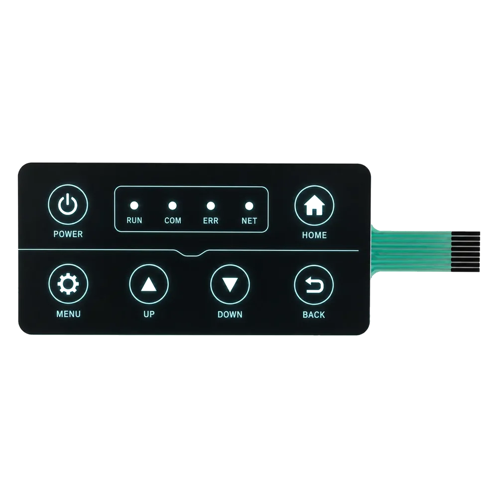
Review graphic overlays →Backlit control panel example
See how LED indicators and dead-front icons are handled in a low-light control panel layout.
View project example →Need a membrane switch that stays readable in low light?
Send your panel dimensions, artwork, key count, backlighting method preference, voltage rail, and operating environment. We will review masking, stack thickness, power supply, and sample feasibility before tooling.
Start RFQ ReviewCompare backlighting options before tooling
Review LED indicators, light guide film, dead-front icons, windows, brightness, and light leakage before sample approval.