
Familia OEM de interruptores de membrana
Interruptores de membrana personalizados — Construidos alrededor del diseno de su producto
Ensamblajes engineer-to-order fabricados desde planos, muestras o especificaciones antes de iniciar el utillaje.
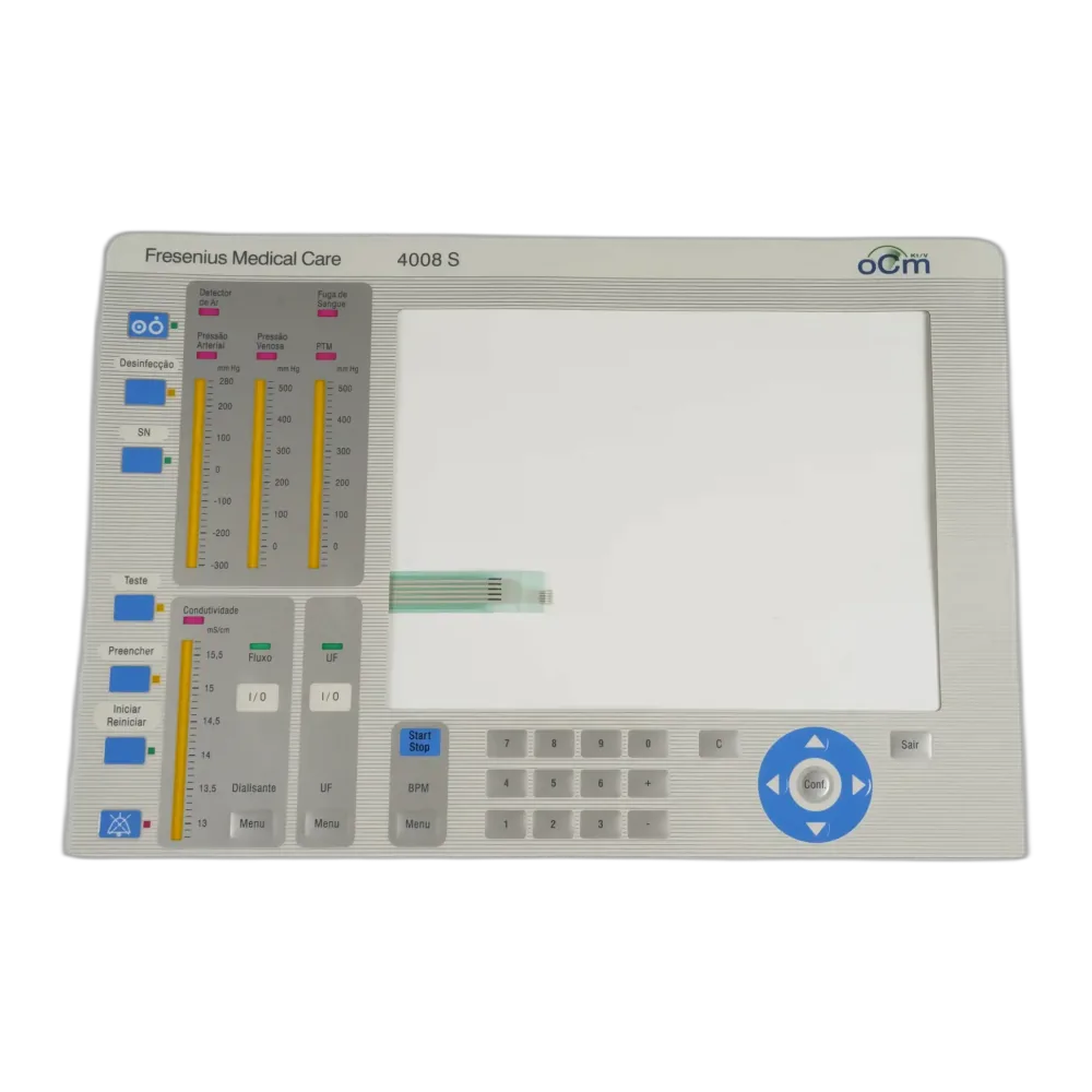
JASPER Electronics fabrica custom membrane switches segun su plano, muestra o especificacion exacta. Como fabricante OEM de custom membrane switch e interruptor de membrana a medida, gestionamos cada capa, overlay grafico, circuito, adhesivo y componente integrado desde una sola fuente.
OEMs que integran nuestros switches en sus equipos


Por que las fallas de switches personalizados se deciden antes de producir
La mayoria de proyectos de interruptor de membrana no empiezan con un plano perfecto. Empiezan con un requisito de producto: un panel que debe soportar 1 millon de actuaciones, encajar en un bisel de 3 mm y cumplir RoHS 2 antes del envio.
When an OEM engineer sends us a layout, our first questions are about actuation force tolerance, adhesive substrate compatibility, connector tail geometry, and environmental exposure. Asi un membrane switch desde plano se convierte en un ensamblaje de produccion repetible, no en una muestra unica. For early-stage programs, our membrane switch design guide and prototyping support help define the stack before tooling.
Empiece por los detalles que deciden la confiabilidad
Envie planos, arte grafico, datos de circuito, fuerza de actuacion objetivo, requisitos de conector y sellado target, overlay material preference, and expected environment. JASPER reviews new OEM custom switch inquiries within 24–48 hours.
Manufacturing and Compliance
Our 2,500 m² area de produccion en sala limpia, also referred to as clean room production space in supplier documentation, keeps particulate contamination out of adhesive bond lines and circuit layers during lamination. Screen printing, die cutting, lamination, and assembly stay in-house so tolerances do not slip through subcontractor handoffs. Every production run can ship with a full inspection report covering dimensional checks, actuation force, and circuit continuity.
Quality management system covering design review, incoming inspection, in-process checks, and final inspection.
EU Directive 2011/65/EU material compliance declaration available on request.
Documentation support for Substances of Very High Concern screening against the current ECHA candidate list.
Material de overlays and adhesives available in UL-recognized grades for UL 508-style panel applications.
Full inspection report, first-article inspection report, lot records, material certificates, and certificate of conformance available when required.
Engineering notes
The three checks to finish before tooling
These decisions belong in design review, not after the first sample fails.
Actuation and life target
Metal domes rated to 1,000,000+ actuations still need the right force window, overlay stack, and spacer thickness for your user interface. FDA-regulated medical device assemblies and CE-marked industrial panels may also require traceability documentation before production release.
Adhesive and environment
Chemical exposure, textured housings, outdoor use, and low-temperature operation can change adhesive selection before sample build.
Connector and tail path
ZIF, FFC, Molex, JST, pitch, bend radius, and tail exit geometry need to match the PCB and enclosure route before tooling.
How a Personalizado Membrane Switch Project Starts
Send AI, PDF, DXF, Gerber, STEP files, a sample, or a rough sketch for layout review.
Within 24–48 hours, JASPER checks registration, trace spacing, connector geometry, overlay bleed, materials, and documentation needs.
Funcionales samples use production materials and processes so your team can test fit, feel, and assembly. Our prototyping workflow supports expedited sample review for time-sensitive programs.
After approval, standard production lead time is 15–20 working days from sample approval. MOQ starts at 500 pieces for most configurations.
Accepted files
Graphic overlay artwork: AI, vector PDF, DXF, Pantone references, CMYK process notes, UV selectivo, and embossing requirements. Circuit data: Gerber RS-274X, DXF, PDF. 3D references: STEP / .stp / .step. ZIF, FFC, Molex, JST, and custom-pitch connector details should be included when available.
Send ArtworkTypical Aplicaciones
Control panels, machine interfaces, sealed operator stations, and field equipment.
Cleanable keypads, documentation support, and controlled production records.
Compact interfaces with custom graphics, tails, and tactile response.
Durable overlays and circuits for service environments and repeated use.
Frequently Asked Questions
Can you work from a sample only, without drawings?
Yes. Send us the physical sample and we will measure and document every dimension, including overlay size, key positions, connector tail length and pitch, and layer stack thickness. We generate a full drawing set from the sample and send it to you for approval before tooling.
Can electronic components such as LEDs, displays, and connectors be integrated into the membrane switch?
Yes. We integrate discrete LEDs, LED arrays, LCD or OLED display windows, tactile domes, and connectors such as ZIF, FFC, Molex, and JST as part of the membrane switch assembly. Component placement is coordinated with your circuit layout during engineering review.
What file formats do you accept for artwork and circuit data?
For graphic overlay artwork, use AI, vector PDF, and DXF. For circuit data, use Gerber RS-274X, DXF, and PDF. For 3D mechanical references, use STEP files including .stp and .step. Raster-only JPEG or PNG files cannot be used as the primary artwork without redrawing.
Related Membrane Switch Recursos
Membrane keypads
Compare custom switch assemblies with sealed keypad builds, dome force, adhesive choice, and tail routing.
View related page →Membrane switch panels
Review larger panel interfaces, windows, LEDs, overlays, and enclosure-ready membrane assemblies.
Explore product →Membrane switch design guide
Prepare drawings, material callouts, connector details, environmental requirements, prototyping needs, and documentation requests before RFQ.
Read guide →Send your drawing, sample, or rough sketch for a custom membrane switch engineering review.
Solicitar cotizacion