
Panel de control de membrana integrado
Personalizado Paneles de interruptores de membrana
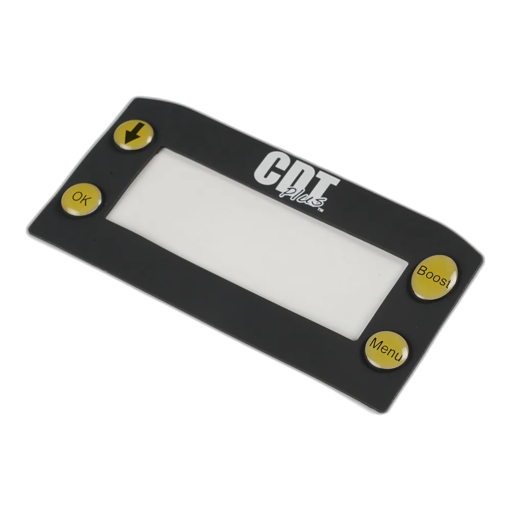
Ensamblajes de panel frontal multitecla que combinan zonas de switch, ventanas de display, indicadores LED y ruta de conector en una interfaz sellada de perfil plano.
Un membrane switch panel es un ensamblaje de control multizona que combina matrices de teclas, ventanas de display, indicadores LED e interfaces de conector en una sola unidad de perfil plano.
OEMs que usan ensamblajes de interfaz JASPER


Respuesta rapida: A diferencia de un membrane keypad independiente, que solo gestiona la conmutacion, un membrane switch panel integra la interfaz completa del operador: entrada, respuesta, ventanas de display, indicadores LED, montaje, sellado y ruta de conector bajo una sola superficie grafica. Los ingenieros OEM especifican paneles cuando el equipo necesita mas que botones.
Mas que un keypad — Una solucion completa de panel frontal
La mayoria de equipos necesita mas que un grupo de teclas. Los operadores leen indicadores de estado, observan displays a traves de ventanas transparentes y usan referencias tactiles para trabajar sin mirar hacia abajo. A membrane switch panel delivers all of that in one laminated assembly — typically 0.5–2.0 mm total thickness — bonded directly to the enclosure.
En JASPER Electronics, los paneles de membrana integrados se fabrican en Dongguan, where screen printing, die cutting, SMT LED placement, and final assembly are coordinated for OEM production run under one roof, with annual output exceeding 3 million panel units across medical, industrial, and transportation programs. We hold ISO 9001:2015 and ISO 14001:2015 certifications, and our products carry UL recognition where required.
The difference between a keypad and a panel is scope. That broader scope is why OEM engineers come to us with a mechanical drawing, not just a key count.
Start with the enclosure, display, and connector details
Send the enclosure drawing, key layout, display-window positions, LED count, electrical interface, connector pitch, and environmental target. JASPER reviews the mechanical fit, circuit route, mounting adhesive, and sealing approach before tooling starts.
What Makes a Panel Different from a Simple Keypad?
What sets a panel apart from a simple keypad: the design starts from the enclosure geometry and the operator’s task — not from the circuit alone.
Where are the keys?
The panel still defines tactile or non-tactile key zones, dome force, spacing, overlay legends, and circuit routing.
Where does the operator read status?
Clear or tinted windows, LCD/OLED cutouts, embedded LEDs, light pipes, and LGF backlighting become part of the same surface.
How does the assembly mount and seal?
Rear adhesive, gasketed bezels, snap-fit frames, tail exit direction, and connector choice are designed around the enclosure.
Manufacturing and Compliance
Production control matters because one finished panel may combine graphics, switch circuits, display windows, LEDs, adhesives, and a connector tail in a single quality record. Screen printing, die cutting, SMT LED placement, and final assembly stay under one roof so those layers are checked together rather than passed between vendors.
Quality management system for design review, production, and inspection.
Environmental management framework for manufacturing operations.
Flammability-rated overlay material options and UL recognition support where required.
IP65 front-face and IP67 perimeter sealing targets for panel projects.
Peel-strength reference for pressure-sensitive adhesive selection.
Vibration, salt spray, humidity, and environmental test references.
Integrated panel stack
This visual explains what the panel combines, not a decorative 3D effect: one front surface, one switching/circuit system, one rear mounting and sealing package.
Prioridades de diseno
Four decisions to finish before tooling
Two factors determine whether a membrane panel succeeds in the field: how well it fits the enclosure, and how well it fits the operator’s task.
Enclosure fit first
We start every panel project with the mechanical drawing of the host enclosure. The panel must align to existing mounting holes, clear internal standoffs, and route the connector tail to the PCB without sharp bends. Silver-ink circuits need a 3 mm minimum bend radius; FPC circuits tolerate 1.5 mm.
Operator workflow
Gloved hands need key spacing of at least 12 mm center-to-center. Low-light panels may need LED backlighting or LGF illumination behind key legends. Panels cleaned with IPA or quaternary ammonium compounds need a chemical-resistant topcoat; standard polyester without hardcoat can degrade after 500 wipe cycles, while hardcoated PET holds past 5,000.
LED thermal management
Surface-mount LEDs placed directly on the circuit layer generate heat. For panels with more than 8 LEDs, we specify copper-flex circuit layers to dissipate heat and maintain forward-voltage stability across the operating temperature range.
Connector routing
The tail exits the panel at a defined location and pitch. We specify the connector exit direction — bottom, right, or rear — before the circuit layout is drawn. ZIF, FFC, crimp housing, or solder-tail termination is matched to the PCB header, with tail length specified to ±2 mm.
How a Mechanical Control Panel Converts to a Membrane Panel
The process has three steps. First, map the existing button and indicator layout — positions, functions, and electrical interface including voltage, current, and connector pinout. Second, we design a membrane panel to the same footprint so it mounts in the existing enclosure cutout without machining changes.
Third, we build a prototype — typically in 5–7 working days — for fit and function verification before production. The result is a panel that weighs roughly 70% less than the mechanical assembly, seals to IP65 or better, and eliminates the mechanical failure modes of individual button stems and indicator lamp sockets.
- 01Mechanical footprint, enclosure cutout, and mounting review
- 02Button, indicator, display-window, and legend mapping
- 03Voltage, current, connector, and pinout confirmation
- 04Layer stack-up, artwork, adhesive, and seal design
- 05Prototype fit check, electrical test, and production release
Typical Uses
Membrane switch panels appear wherever an operator interface must be flat, sealed, and durable. The following application categories account for the majority of our production volume, each with distinct environmental and electrical requirements.
Industrial HMI
Machine control panels for CNC equipment, PLCs, and conveyor systems. Typical spec: IP65 front seal, tactile domes 250 gf, operating temp −20 °C to +70 °C, and panel sizes from 150 × 100 mm to 400 × 300 mm.
Medical devices
Infusion pumps, patient monitors, and diagnostic instruments. Panels require chemical resistance to IPA and bleach wipes, UL 94 V-0 overlay material, biocompatibility-compliant adhesives, and documentation packages for FDA 510(k) submissions.
Laboratory and test equipment
Analytical instruments and benchtop testers. These panels often carry 30–60 keys plus multiple display windows for LCD readouts; FPC circuits handle the high pin count, and ZIF connectors allow field replacement.
Food and beverage processing
Filling lines, mixers, and packaging machines facing wash-down with high-pressure water, sodium hypochlorite exposure, and caustic cleaners. We specify IP67 full-perimeter seals and chemical-resistant topcoats.
Transportation and marine
Vehicle dashboards, marine helm stations, and rail operator consoles using UV-stable inks that prevent legend fade after 1,000+ hours of direct sunlight, with salt-spray resistance per IEC 60068-2-11.
Building automation
HVAC controllers, access panels, and lighting control stations. These panels typically run under 100,000 cycles but need 10+ years of service life, so we specify UV-stable overlays and 3M VHB mounting adhesive.
Defense and aerospace
Operator consoles for ground support equipment and vehicle systems requiring MIL-STD-810 environmental compliance, NVIS Class B backlighting, and full traceability documentation from raw material to finished assembly.
Request a Personalizado Panel Quote
Send us your enclosure drawing, key layout, and connector requirements. We return a DFM review and price within 2 business days. Prototypes ship in 5–7 working days from drawing approval. Production lead time is 15–25 working days depending on panel complexity and order quantity. MOQ is 50 units for standard configurations; lower quantities are available for prototype and pilot production runs.
What to send
- Enclosure drawing and panel footprint
- Key layout, legends, and display-window locations
- LED count, light-pipe or LGF expectations
- Voltage, current, connector pitch, and pinout
- IP rating, cleaning protocol, temperature range, and order quantity
Related product context
- graphic overlays for printed surface, windows, textures, and hardcoat decisions
- membrane switches for circuit, dome, adhesive, and tail-routing options
- control panel overlays are currently planned and should be linked after the page is published
- membrane switch design guide for drawing and material preparation
Frequently Asked Questions
What is the difference between a membrane switch panel and a single membrane keypad?
A membrane keypad is a standalone array of switch keys — it handles switching only. A membrane switch panel is a complete front-panel assembly: it combines key zones, display windows, LED indicators, and a connector interface into one laminated unit. The panel is designed to the enclosure geometry and covers the full operator-facing surface of the equipment. A keypad is a component; a panel is a finished interface.
Can I integrate buttons, display windows, and LEDs in one membrane panel?
Yes. A typical integrated panel combines 10–50+ key positions, one to four clear or tinted display windows, and embedded LEDs or LGF backlighting — all on a single polyester substrate with one graphic overlay on top. The circuit layer routes LED drive lines alongside switch circuits to a single connector tail. JASPER has produced panels with 64 keys, three LCD windows, and 12 status LEDs as a single assembly, 1.8 mm total thickness.
How do I convert a mechanical control panel to a membrane switch panel?
The process has three steps. First, map the existing button and indicator layout — positions, functions, and electrical interface. Second, we design a membrane panel to the same footprint so it mounts in the existing enclosure cutout without machining changes. Third, we build a prototype, typically in 5–7 working days, for fit and function verification before production.
Related Membrane Switch Recursos
graphic overlays
Review overlay materials, print durability, windows, textures, and display-surface requirements.
Explore product →membrane switches
Compare panel builds with broader membrane switch constructions, circuits, adhesives, and sealing options.
View product family →membrane switch design guide
Prepare drawings, material callouts, connector details, and environmental requirements before RFQ.
Read guide →Send your enclosure drawing, key layout, display-window positions, LED count, and connector requirements for DFM review.
Request a Personalizado Panel Quote