
Familia OEM de interruptores de membrana
Personalizado Teclados de membrana for OEM Control Interfaces
Ensamblajes de keypad sellados, disenados segun fuerza de domo, seleccion de adhesivo y ruta de cola antes de iniciar el utillaje.
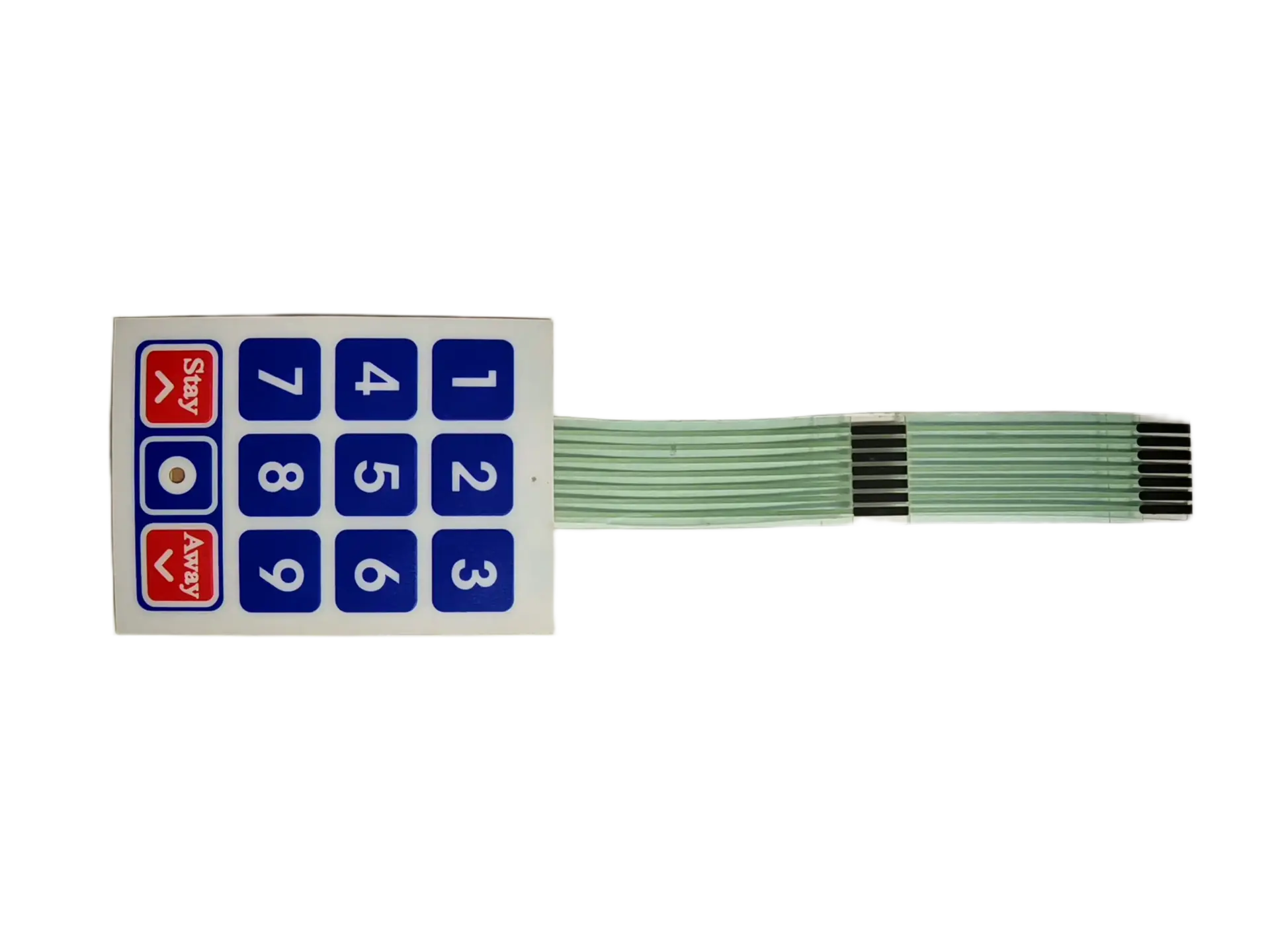
Un membrane keypad personalizado combina overlay grafico impreso, circuito con domo tactil o no tactil y cola sellada con conector en un conjunto delgado listo para integrar en su interfaz de control.
OEMs que integran nuestros switches en sus equipos


Por que la mayoria de fallas del keypad se deciden antes de producir
Tres causas explican la mayoria de fallas de campo en keypads OEM devueltos: fuerza de domo fuera de especificacion, delaminacion del adhesivo y grietas por doblado de cola. None of them happen on the production floor; they are designed in during the specification stage.
When an OEM engineer sends us a layout, our first questions are about actuation force tolerance, adhesive substrate compatibility, and tail routing geometry. Get those three right at the drawing stage, and the keypad will outlast the product it controls.
Empiece por los detalles que deciden la confiabilidad
Envie planos mecanicos, requisitos de conector, pinout, fuerza de actuacion objetivo, nivel de sellado, material de overlay preferido y entorno esperado. JASPER revisa nuevas consultas OEM de keypads dentro de un dia habil.
Manufacturing and Compliance
Our 2,500 m² cleanroom keeps particulate contamination out of adhesive bond lines and circuit layers during lamination. Incoming silver ink and adhesive lots are tested before release to production, with full material traceability from raw film stock through finished assembly.
Quality management system covering design, production, and inspection.
EU Directive 2011/65/EU material compliance declaration available on request.
No substances of very high concern above 0.1% w/w in selected material systems.
Flame-retardant overlay and circuit substrate material options for qualified projects.
First-article inspection reports and PPAP documentation available for automotive and medical customers.
Engineering notes
The three failures to prevent at spec stage
These checks belong in design review, not after tooling is cut.
Dome force out of tolerance
Metal domes are commonly specified at 160 gf, 200 gf, 260 gf, or 320 gf, but supplier tolerance can be ±15%. JASPER can inspect incoming lots to a tighter agreed window, such as ±10%, before lamination.
Adhesive delamination
PET and PC overlays do not bond the same way. For thermal cycling, specify 3M 9080 or equivalent and request test evidence such as 50 cycles from –40 °C to +85 °C before production release.
Tail-bend cracking
The minimum safe bend radius is 6× tail thickness. A 0.125 mm PET tail needs at least 0.75 mm radius, silver ink should avoid the bend zone, and connector crimp should stay 5 mm away from the first bend.
How a Personalizado Membrane Keypad Project Starts
We start from your mechanical envelope and electrical interface, then design each layer to match the connector type, pin-out, actuation force, and Grado IP. Tooling lead time is typically 10–15 business days; production samples follow within 3–5 days of tooling approval.
Production can include visual standards, electrical test records, force-displacement curves, peel-strength checks, FAIR, and PPAP documentation depending on the application.
- 01Mechanical envelope and artwork review
- 02Conector, pin-out, and tail routing confirmation
- 03Fuerza de actuacion and Grado IP specification
- 04Layer stack-up, tooling, and first-article sampling
- 05Electrical, visual, force, and adhesive inspection
Typical Aplicaciones
Medical devices
Patient monitors, infusion pumps, and diagnostic analyzers using IP65 sealing and chemical-resistant overlays for repeated cleaning.
Industrial control panels
PLCs, motor drives, and HVAC controllers with copper flex options and IP67 gasket seals for wash-down environments.
Test and measurement
Handheld analyzers and bench-top testers that need tight dome-force tolerances and ESD-protective overlays.
Inicio appliances
Washing machines, ovens, and air purifiers using cost-optimized carbon ink circuits and EL backlighting where required.
Fitness equipment
Treadmill consoles and elliptical displays with sweat-resistant hard-coat overlays and LED visibility under gym lighting.
Kiosks and vending machines
Ticketing terminals and self-service panels using vandal-resistant PC overlays, selective gloss legends, and IP54 sealing.
Frequently Asked Questions
What is a membrane keypad and how is it custom-built for OEM products?
A membrane keypad is a multi-layer input device in which key presses are registered by flexing a top membrane layer down onto a conductive circuit layer, completing an electrical circuit. The standard construction is: graphic overlay, top spacer, dome retainer, circuit spacer, bottom circuit layer, and mounting adhesive. For OEM customization, JASPER starts from the mechanical envelope and electrical interface, including connector type, pin-out, actuation force, and Grado IP, then designs each layer to match.
What options are available when ordering a custom membrane keypad?
The main options are overlay material, key feel, circuit type, backlighting, adhesive, connector, surface finish, and protection rating. Typical choices include PET or PC overlays, non-tactile or 100–400 gf metal dome tactile keys, silver ink or copper flex circuits, 3M 467MP or 9080 adhesives, ZIF or FFC tails, and IP40 through IP67 protection. Secondary options include Braille embossing, selective gloss key legends, EMI shielding layers, and rigid backer plates.
How do I avoid dome-force and tail-bend failures in a membrane keypad?
For dome force, specify the target actuation force and tolerance window, confirm silver ink thickness uniformity, and request a force-displacement curve on first-article samples. For tail bending, enforce a minimum bend radius of 6× tail thickness, route silver ink traces around the bend zone, and keep connector terminations at least 5 mm from the first bend. Both failure modes are preventable at the design review stage.
Related Membrane Switch Recursos
Personalizado membrane switches
See the broader membrane switch assembly options that support custom keypad builds.
Explore product →Membrane switch panels
Compare keypad layouts with larger panel interfaces, windows, LEDs, and enclosure-ready assemblies.
View related page →Membrane switch design guide
Prepare drawings, material callouts, connector details, and environmental requirements before RFQ.
Read guide →Send your keypad drawing, connector requirement, and actuation force spec for engineering review.
Solicitar cotizacion