

Table of Contents
- Introduction
- Manufacturing Process Overview
- Raw Materials and Preparation
- Screen Printing Process
- Die-Cutting and Laser Cutting
- Assembly and Lamination
- Embossing and Surface Forming
- Quality Control and Testing
- Production Capabilities and Lead Times
- Customization and Prototyping
- Frequently Asked Questions
Quick Answer: Membrane switch manufacturing involves a multi-stage process: (1) screen printing graphics on overlay substrates (polyester/polycarbonate) using UV-cured inks with registration tolerance ±0.25mm, (2) screen printing conductive circuits with silver ink (0.01-0.05 Ω/sq resistance) on polyester substrates, (3) die-cutting or laser-cutting all layers (overlay, adhesive, spacer, circuit, backer) with ±0.25mm tolerance, (4) precision assembly/lamination in cleanroom environment bonding layers with pressure rollers, (5) embossing overlay for tactile features using heated molds (150-180°C), (6) comprehensive quality inspection (visual, electrical, dimensional, environmental testing). Lead times range from 2-3 weeks for prototypes to 4-8 weeks for production volumes. Manufacturing requires specialized equipment (screen printers, die-cutting presses, lamination systems), ISO 9001 quality systems, and industry-specific certifications (ISO 13485 for medical, IATF 16949 for automotive).
Manufacturing membrane switches combines traditional printing craftsmanship with modern precision engineering. Unlike mass-produced electronic components, each membrane switch is essentially a custom-manufactured product tailored to specific application requirements. Understanding the manufacturing process helps engineers design better products, set realistic expectations for quality and lead times, and communicate effectively with manufacturers.
After 15 years managing production operations at JASPER Display, I've overseen the manufacture of over 10 million membrane switch assemblies across medical, industrial, automotive, and consumer applications. This comprehensive guide reveals the manufacturing processes, quality control measures, and production considerations that determine membrane switch performance, reliability, and cost.
Manufacturing Process Overview
Membrane switch production follows a systematic sequence of specialized processes, each requiring specific equipment, materials, and quality controls.
Complete Manufacturing Sequence:
- Pre-production (Days 1-3): Design review, artwork preparation, screen preparation, material procurement, production planning
- Screen printing - Graphics (Days 4-6): Print overlay graphics (1-5 colors), UV cure each layer, inspection
- Screen printing - Circuits (Days 5-7): Print conductive traces and contact pads, oven cure, resistance testing
- Die-cutting (Days 8-10): Cut overlay, adhesive layers, spacer, circuit, backer to precise dimensions
- Embossing (Days 9-11): Form tactile features on overlay using heated dies (if specified)
- Assembly (Days 11-13): Layer-by-layer lamination with dome placement, pressure bonding
- Testing (Days 14-15): Electrical testing, visual inspection, environmental testing (sample basis)
- Packaging (Day 16): Protective packaging, labeling, documentation, shipment preparation
Critical Process Parameters:
- Registration accuracy: ±0.25mm alignment between print layers and die-cut features
- Print resolution: 150-300 DPI for graphics, ±0.1mm line width control for circuits
- Cure completeness: 95%+ ink cure for chemical resistance and adhesion
- Adhesive bond strength: >1000 g/25mm peel strength for overlay-to-circuit bond
- Dome retention: Domes must remain centered ±0.5mm during assembly and service life
- Cleanliness: Class 100,000 (ISO 8) cleanroom for assembly prevents contamination-induced failures
Raw Materials and Preparation
Material quality and consistency directly impact membrane switch performance, making supplier qualification and incoming inspection critical.
Substrate Materials
Substrate films form the foundation of membrane switch construction—graphic overlay and circuit layers.
Polyester (PET) Films:
- Standard thicknesses: 0.125mm (5 mil), 0.175mm (7 mil), 0.250mm (10 mil)
- Surface treatments: Matte (AG - anti-glare), Velvet (textured), Gloss, Hard coat (3H-8H pencil hardness)
- Dimensional stability: <0.1% shrinkage after printing/curing critical for registration
- Common grades: Autotype, DuPont Teijin (Melinex), Toray, SKC Films
- Cost: $2-6 per square meter depending on thickness and treatment
Polycarbonate (PC) Films:
- Standard thicknesses: 0.175mm (7 mil), 0.250mm (10 mil), 0.375mm (15 mil), 0.500mm (20 mil)
- Advantages: Superior chemical resistance, higher impact strength, better dimensional stability at temperature extremes
- Surface options: Matte, Gloss, Velvet, Hard coat (UV-cured polysiloxane coating), Antimicrobial
- Common grades: SABIC Lexan, Covestro Makrofol, Teijin Panlite
- Cost: $8-20 per square meter (2-3× polyester cost)
Incoming Material Inspection:
- Visual inspection for scratches, inclusions, surface defects
- Thickness measurement (±10% tolerance verification using micrometer)
- Surface energy testing (dyne pens or contact angle) ensures adequate ink adhesion (>38 dynes/cm minimum)
- Dimensional stability testing (pre/post thermal cycling measurement)
- Lot tracking and traceability documentation (especially critical for medical and automotive)
Conductive Inks
Conductive inks create the electrical circuits enabling switch functionality.
Silver Ink Formulations:
- Composition: Silver flakes (60-80% by weight) + polymer binder + solvent carrier
- Sheet resistance: 0.01-0.05 Ω/sq (ohms per square) for standard applications
- Cure profile: Thermal cure 120-150°C for 10-30 minutes, or UV cure for rapid processing
- Adhesion: >4B pencil hardness cross-hatch adhesion test to polyester substrate
- Flexibility: Maintain conductivity through 100,000+ flexing cycles (1mm radius mandrel bend test)
- Environmental stability: <5% resistance change after 1000 hours 85/85 humidity aging
- Common suppliers: DuPont, Henkel, Acheson (DAG), Sun Chemical
Specialized Ink Types:
- Carbon ink: High resistance (1-10 kΩ/sq), lower cost, pressure-sensitive applications
- Silver/carbon blends: Mid-range resistance (10-100 Ω/sq), better stability than pure silver
- Dielectric inks: Insulating inks for crossover traces, capacitive touch sensing
- Solder mask inks: Protective coating over silver traces prevents oxidation
Ink Quality Control:
- Viscosity measurement (Brookfield viscometer): 8,000-15,000 cps typical for screen printing
- Print test panels for each new ink batch verifying conductivity, adhesion, cure characteristics
- Shelf life tracking (6-12 month typical shelf life, refrigerated storage extends life)
- Lot-to-lot consistency verification (resistance, color, printability)
Adhesive Systems
Membrane switches typically incorporate 3-5 adhesive layers bonding components together.
Common Adhesive Types:
| Application | Adhesive Type | Typical Product | Key Characteristics |
|---|---|---|---|
| Overlay to circuit bonding | Acrylic transfer adhesive | 3M 467MP, 468MP | High shear strength, 0.05mm thickness, excellent clarity |
| High-temperature applications | Acrylic (high-temp) | 3M 9731, 9495MP | -40°C to +150°C, automotive under-hood use |
| Dome retention | Low-tack acrylic or silicone | Custom formulation | Holds dome in position while allowing movement during actuation |
| Spacer layer (double-sided) | Acrylic on polyester carrier | 3M 9495MP | 0.125-0.175mm total thickness, dimensionally stable |
| Panel mounting adhesive | High-performance acrylic | 3M 468MP, VHB | 1500+ g/25mm peel strength, conformable to surface irregularities |
| Medical/biocompatible | Medical-grade silicone | 3M 355, Adhesives Research | ISO 10993 biocompatibility, USP Class VI |
Adhesive Storage and Handling:
- Climate-controlled storage: 18-24°C, 40-60% RH prevents premature curing or degradation
- Acclimation period: 24-48 hours at room temperature before use prevents air bubbles from temperature shock
- Shelf life tracking: 6-12 months typical, FIFO (first-in-first-out) inventory management
- Liner cleanliness: Silicone release liners must be dust-free to prevent contamination during lamination
Tactile Dome Components
Metal domes provide the tactile "snap" feedback characteristic of quality membrane switches.
Dome Specifications:
- Material: Stainless steel (typically 301 or 304 grade), 0.05-0.10mm thickness
- Plating: Gold (best conductivity, highest cost), nickel (standard), or tin (economy)
- Diameters: 6mm, 8mm, 10mm, 12mm, 15mm (custom sizes available)
- Actuation force: 150-450gf (gram-force), ±20gf tolerance
- Force ratio: >60% snap ratio (peak force ÷ final force) for definitive tactile feel
- Life cycle: 5-20 million actuations depending on force rating and quality
- Suppliers: Snaptron, Best Technology, ITW Switches
Dome Quality Inspection:
- Force testing: 100% automated testing measures peak force, snap ratio, travel distance
- Visual inspection: Automated optical inspection detects surface defects, plating issues
- Dimensional verification: Height, diameter measurements ensure proper fit in spacer windows
- Life cycle sampling: Statistical sampling subjects domes to 10+ million cycles verifying durability
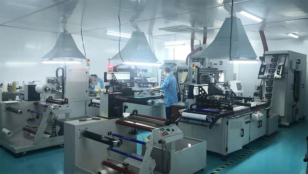
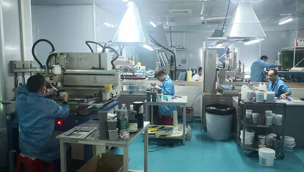
Screen Printing Process
Screen printing transfers graphic and conductive inks onto substrate films with precision and repeatability.
Graphic Overlay Printing
Graphic printing creates the user-facing visual interface on the overlay layer.
Screen Preparation:
- Mesh selection: 200-305 mesh count (threads per inch) for fine detail graphics, 150-200 mesh for solid flood coats
- Emulsion coating: Photo-sensitive emulsion coated on mesh, dried in dark room
- Exposure: Artwork film (positive) placed on screen, UV exposed to harden emulsion except image areas
- Washout: Unexposed emulsion washed away leaving open mesh in image areas
- Touch-up and inspection: Pinholes filled, registration marks verified
- Screen life: 5,000-50,000 prints per screen depending on ink type and design complexity
Printing Process:
- Substrate loading: Polyester or polycarbonate film secured to vacuum table or registration pins
- Screen registration: Screen aligned to substrate using optical registration marks (±0.1mm accuracy)
- Ink flooding: Ink spread across screen using flood bar
- Squeegee stroke: Rubber squeegee (60-80 durometer) forces ink through open mesh onto substrate
- Screen lift: Screen separates from substrate (snap-off distance 2-5mm)
- Inspection: Visual check for complete print coverage, no voids or smearing
Multi-Color Printing:
- Each color requires separate screen and print pass
- Registration tolerance: ±0.25mm between colors (visible misalignment at ±0.5mm)
- Cure/dry each color before printing next layer to prevent mixing
- Typical color sequence: lightest colors first, black outlines last for crisp edges
Second-Surface Printing:
- Graphics printed on reverse (second surface) of overlay for abrasion protection
- Requires mirror-image artwork
- Print sequence reversed: outlines first, flood coats last
- Final appearance viewed through overlay thickness (0.175-0.375mm)
Circuit Layer Printing
Circuit printing deposits conductive silver ink forming switch contacts and interconnect traces.
Circuit Print Considerations:
- Substrate preparation: Clean polyester substrate (isopropyl alcohol wipe), corona or flame treatment increases surface energy for ink adhesion
- Mesh selection: 230-325 mesh for fine traces (0.5mm width), 150-200 mesh for contact pads and heavy deposits
- Ink viscosity: 10,000-15,000 cps optimized for screen printing (lower viscosity flows better, higher viscosity deposits thicker layer)
- Print thickness: 8-15 microns wet thickness (after cure: 5-10 microns dry)
- Registration: Critical alignment of upper and lower circuit contacts (±0.25mm tolerance)
Circuit Quality Requirements:
- Trace continuity: 100% electrical continuity, no breaks or thin spots
- Resistance consistency: <10% variation trace-to-trace within same circuit
- Edge definition: Clean, straight trace edges without feathering (±0.1mm edge tolerance)
- Contact pad uniformity: Consistent ink deposit thickness across pad area for reliable switching
Curing and Drying
Proper curing ensures complete ink polymerization for optimal performance and durability.
UV Curing (Graphic Inks):
- UV dose: 200-600 mJ/cm² depending on ink formulation and thickness
- Wavelength: 365nm peak (UVA range) typical for screen printing inks
- Conveyor speed: 5-20 meters/minute through UV tunnel
- Verification: Solvent rub test (50 double rubs with MEK or isopropyl alcohol shows no ink removal when fully cured)
- Advantages: Instant cure, low heat input (substrate doesn't distort), high throughput
Thermal Curing (Conductive Inks):
- Temperature profile: 120-150°C for 10-30 minutes (varies by ink formulation)
- Oven type: Convection or IR ovens with precise temperature control (±5°C)
- Cure verification: Resistance measurement (<5% change after additional 10 minutes at cure temperature indicates complete cure)
- Adhesion test: Cross-hatch tape test (ASTM D3359) shows >95% ink retention after cure
Environmental Conditions:
- Print room: 20-24°C, 45-55% RH prevents ink drying in screen or excessive solvent evaporation
- Cure area ventilation: Exhaust fumes from solvent evaporation and thermal curing
- Post-cure handling: 24-hour room temperature stabilization before die-cutting prevents dimensional changes
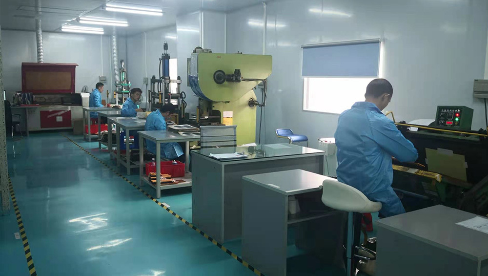
Die-Cutting and Laser Cutting
Precision cutting shapes all membrane switch layers to final dimensions and features.
Steel Rule Die-Cutting:
- Die construction: Hardened steel cutting rules (0.5-2mm wide) mounted in plywood or metal base
- Die-cutting press: Hydraulic or pneumatic press (5-50 tons pressure) with precision platens
- Cutting accuracy: ±0.25mm typical, ±0.15mm achievable with tight tolerance dies
- Features cut: Outline shape, button windows, mounting holes, alignment holes, connector tail shape
- Die life: 50,000-500,000 impressions depending on material hardness (polycarbonate wears dies faster than polyester)
- Cost: $300-1,500 per die depending on size and complexity
Rotary Die-Cutting:
- Method: Cylindrical die with cutting rules rotates against anvil cylinder
- Advantages: High-speed continuous cutting (50-100 parts/minute vs 10-20 for flatbed)
- Applications: High-volume production (>10,000 units), simpler geometries
- Setup cost: $2,000-5,000 per die (higher than flatbed but amortized over high volumes)
Laser Cutting:
- Laser types: CO₂ laser (10.6 micron wavelength) for polyester and polycarbonate
- Accuracy: ±0.05mm achievable, superior to die-cutting for intricate features
- Advantages: No tooling cost (CAD file drives laser path), perfect for prototypes and low volumes, complex geometries
- Disadvantages: Slower than die-cutting (5-10 parts/minute), heat-affected zone may discolor edges, higher cost per part at volume
- Edge quality: Smooth melted edge (no burrs like die-cutting), slight brown discoloration on polycarbonate edges
Process Selection:
- Prototypes (1-25 units): Laser cutting (no tooling cost, fast turnaround)
- Low volume (25-1,000 units): Steel rule die-cutting (economical tooling, adequate speed)
- Medium volume (1,000-10,000 units): Steel rule die-cutting with multiple-up dies (cut multiple parts per stroke)
- High volume (>10,000 units): Rotary die-cutting (fastest throughput, lowest per-part cost)
Assembly and Lamination
Assembly combines individual layers into the complete membrane switch structure through precision lamination.
Cleanroom Requirements:
- Classification: ISO Class 8 (Class 100,000) minimum for assembly, ISO Class 7 (Class 10,000) for medical devices
- Contamination control: HEPA-filtered air, positive pressure, sticky mats, lint-free garments, gloves
- Purpose: Prevent dust particles between layers causing bubbles, electrical shorts, or cosmetic defects
Layer-by-Layer Assembly Sequence:
- Backer layer placement: Position backer (polyester or rigid substrate) on assembly fixture with registration pins
- Lower circuit application: Remove adhesive liner, align lower circuit using registration holes, apply with roller to eliminate air bubbles
- Spacer layer lamination: Apply spacer with die-cut button windows, precise alignment critical (±0.3mm tolerance)
- Dome placement: Position tactile domes in spacer windows using vacuum pick-and-place or manual tweezers (centered ±0.5mm)
- Upper circuit application: Align upper circuit so contact pads register with domes and spacer windows
- Overlay lamination: Final overlay layer applied with graphic alignment to embossed features and button locations
- Pressure rolling: Lamination roller (10-20 kg pressure) or pneumatic press ensures complete adhesive bond
Lamination Equipment:
- Manual lamination: Hand roller application, suitable for prototypes and low volumes (<100 units/day)
- Semi-automatic: Vacuum table, precision alignment fixtures, pneumatic press (100-500 units/day)
- Automatic lamination: Vision-guided alignment, automated peel-and-stick, production rates >1,000 units/day
Critical Assembly Parameters:
- Registration accuracy: Dome center to spacer window center ±0.5mm, circuit-to-circuit contact alignment ±0.3mm
- Adhesive bond pressure: 15-20 PSI applied for 15-30 seconds achieves >90% bond strength immediately
- Cure time: 24-72 hours at room temperature for full adhesive strength development
- Air bubble elimination: Roller technique or vacuum lamination prevents trapped air (bubbles cause cosmetic defects and potential delamination)
Connector Attachment:
- Stiffener application: Polyimide or FR4 stiffener adhered to tail connector area for ZIF connector insertion rigidity
- Tail folding: Precision folding if tail routes back under switch (avoid sharp creases that crack conductors—minimum 3mm radius)
- Overmolding: Silicone or polyurethane overmold on connector (for IP67+ applications) requires secondary molding operation
Embossing and Surface Forming
Embossing creates raised tactile features on the overlay surface enhancing user experience.
Embossing Methods:
1. Male/Female Die Embossing (Most Common):
- Tooling: Matched male and female metal dies machined to button shape
- Process: Overlay placed between dies, heated to forming temperature (150-180°C for polycarbonate, 120-140°C for polyester), pressure applied (50-200 PSI), cooled while maintaining pressure
- Emboss height: 0.3-0.8mm typical, limited by material thickness and properties
- Cycle time: 30-60 seconds per panel (heat, dwell, cool)
- Die cost: $500-2,000 per die set depending on complexity
2. Vacuum Forming:
- Process: Overlay heated and drawn over male mold using vacuum, suitable for large-area forming or deep draws
- Advantages: Lower tooling cost than matched dies, can form larger areas
- Limitations: Less precise than die embossing, material thinning at high points
3. Hydraulic Forming:
- Process: Fluid pressure forces overlay into female die cavity, used for complex 3D shapes
- Applications: Automotive trim panels, complex ergonomic shapes
Embossing Design Rules:
- Corner radius: 1.5-2mm minimum to prevent stress concentration and tearing
- Draft angle: 3-5° sidewall taper facilitates mold release
- Web distance: Minimum 3mm between adjacent embossed features prevents material tearing
- Material thickness: 0.250mm minimum for emboss depths >0.5mm (thinner materials tear or wrinkle)
- Emboss-to-print registration: ±0.5mm achievable between embossed button and printed graphic
Quality Inspection:
- Visual inspection: Uniform emboss height, no wrinkling, creasing, or tearing
- Dimensional verification: Emboss height measurement (±0.1mm tolerance typical)
- Optical inspection: Verify emboss-to-print alignment within tolerance
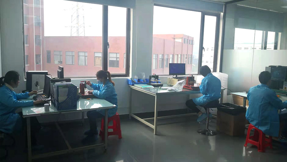
Quality Control and Testing
Comprehensive quality control throughout production ensures membrane switches meet performance specifications.
In-Process Quality Checks:
Screen Printing Stage:
- Color verification using spectrophotometer (ΔE <2.0 from Pantone standard)
- Print registration check (±0.25mm between colors)
- Cure verification (solvent rub test, UV dose measurement)
- Visual inspection for voids, pinholes, smearing (100% inspection or statistical sampling)
Circuit Printing Stage:
- Resistance measurement: Four-wire measurement of trace resistance (target <100Ω, ±10% tolerance)
- Continuity testing: 100% automated testing verifies no broken traces
- Insulation testing: Megohm-meter verifies >10 MΩ between adjacent traces
- Visual inspection: Automated optical inspection (AOI) detects print defects
Die-Cutting Stage:
- Dimensional inspection: Caliper or CMM measurement of critical dimensions (±0.25mm tolerance)
- Edge quality: Visual check for clean cuts, no burrs or material tags
- Hole location: Verify alignment holes and mounting holes within tolerance
Assembly Stage:
- Layer registration: Optical inspection verifies dome-to-window alignment, circuit-to-circuit alignment
- Bubble detection: Visual inspection under angled lighting detects trapped air
- Adhesion verification: Peel test on sample units (>1000 g/25mm required)
Final Inspection and Testing:
Electrical Testing (100% Testing):
- Actuation testing: Automated tester actuates each button, verifies electrical contact closure
- Force measurement: Statistical sampling measures actuation force (target ±20% of specification)
- Contact resistance: Four-wire measurement <100Ω when actuated
- Insulation: >10 MΩ between contacts when not actuated
- Connector continuity: Verify continuity from each button to appropriate connector pin
Visual Inspection (100%):
- Graphic quality: Color consistency, registration, no scratches or defects
- Dimensional accuracy: Overall dimensions, hole locations within tolerance
- Cleanliness: No dust, fingerprints, or contamination
- Embossing quality: Uniform height, no wrinkles or distortion
Environmental Testing (Sample Basis):
- Temperature cycling: -40°C to +85°C, 10+ cycles, verify no delamination or electrical failure
- Humidity aging: 85°C / 85% RH for 168-1000 hours, resistance change <10%
- Life cycle testing: Actuate samples to 1-5 million cycles, verify performance at end of life
- Adhesion testing: 90° peel test after environmental exposure, >80% of initial strength
- Chemical resistance: Expose to specified chemicals (isopropyl alcohol, cleaners), verify no graphic degradation
Quality Documentation:
- Certificate of Conformance (C of C) documenting compliance to specifications
- Inspection reports with actual measurement data
- Material traceability (lot numbers for substrates, inks, adhesives, domes)
- Environmental test reports (for qualification builds)
- First Article Inspection Reports (AS9102 for aerospace, PPAP for automotive)
Production Capabilities and Lead Times
Understanding manufacturing capabilities and realistic timelines helps set appropriate expectations.
Production Volume Capabilities:
| Production Type | Quantity Range | Manufacturing Method | Typical Lead Time | Unit Cost Range |
|---|---|---|---|---|
| Prototype | 1-25 units | Digital printing, laser cutting, manual assembly | 5-10 business days | $50-$300 each |
| Pilot production | 25-500 units | Screen printing, steel rule dies, semi-auto assembly | 2-4 weeks | $10-$50 each |
| Low volume production | 500-5,000 units | Production screen printing, steel rule dies, semi-auto | 4-6 weeks | $3-$15 each |
| Medium volume production | 5,000-50,000 units | High-speed printing, rotary dies, automated assembly | 6-8 weeks | $1-$8 each |
| High volume production | >50,000 units | Fully automated lines, rotary dies, robotic assembly | 8-12 weeks (initial) | $0.50-$5 each |
Lead Time Breakdown (Typical Low-Volume Production):
- Design review and artwork prep: 2-3 days
- Screen preparation: 2-3 days (1 day per color, parallel processing)
- Material procurement: 3-7 days (stock materials) or 2-4 weeks (custom materials)
- Printing and curing: 3-5 days (graphics and circuits)
- Die fabrication: 5-10 days (steel rule dies) or same-day (laser cutting)
- Die-cutting: 1-2 days
- Embossing tooling: 7-14 days (if required)
- Assembly and lamination: 2-4 days
- Testing and inspection: 1-2 days
- Packaging and shipment: 1 day
- Total: 4-6 weeks typical for production quantities with new tooling
Factors Affecting Lead Time:
- Expedite options: Rush service (2-3 week delivery) available at 25-50% premium
- Repeat orders: 2-3 weeks possible when tooling exists and materials in stock
- Complex designs: Multiple embossing features, >5 colors, backlighting add 1-2 weeks
- Compliance testing: Environmental testing, certification testing adds 2-6 weeks
- Custom materials: Non-standard substrates, special adhesives extend lead time 2-4 weeks
Production Capacity:
- Small manufacturer: 10,000-50,000 panels/month capacity
- Medium manufacturer: 50,000-500,000 panels/month capacity
- Large manufacturer: 500,000-5,000,000+ panels/month capacity
- Scalability: Production ramps over 3-6 months for new high-volume programs
Customization and Prototyping
Effective prototyping accelerates product development while controlling costs.
Prototype Options:
1. Digital Print Prototypes:
- Method: UV inkjet or solvent printer prints graphics directly on overlay substrate
- Advantages: No screen tooling cost, 3-5 day turnaround, perfect for design iterations
- Limitations: Colors may not match production Pantone exactly, less durable than screen-printed inks, texture difference
- Cost: $100-200 per panel for quantities 5-10
- Best for: Initial design validation, user testing, form-fit-function verification
2. Screen-Printed Prototypes:
- Method: Production screen printing process with prototype screens
- Advantages: Production-representative graphics, accurate color matching, durability testing possible
- Costs: $150-300 per color for screens, plus $50-100 per panel
- Quantity: Economic for 10-50 prototypes when production color accuracy required
- Best for: Design verification before production tooling commitment
3. Hybrid Prototypes:
- Method: Digital print graphics + production circuits + laser-cut layers
- Advantages: Functional electrical testing with fast-turnaround graphics
- Best for: Engineering validation testing (EVT) before design freeze
Prototyping Best Practices:
- Start with digital prototypes for rapid design iteration (test multiple layouts in parallel)
- Progress to screen-printed prototypes once design stabilized for color/durability validation
- Order 10-25 prototypes minimum to allow destructive testing (environmental, life cycle) while preserving samples
- Test with actual users in target environment (gloved operation, lighting conditions, tactile feedback)
- Document changes between prototype iterations to prevent reverting to abandoned design directions
Design Iteration Cycle:
- Iteration 1: Digital print prototype, user testing, layout adjustments (1-2 weeks)
- Iteration 2: Refined digital prototype with corrected tactile forces, dome sizes (1-2 weeks)
- Iteration 3: Screen-printed prototype with production colors, materials, full functional testing (3-4 weeks)
- Design freeze: Lock design, create production tooling, pilot build (6-8 weeks)
- Design validation: Production representative samples, comprehensive testing, certification (4-8 weeks)
Customization Capabilities:
- Custom shapes and sizes (any size within press capacity 300mm × 450mm typical)
- Custom colors (any Pantone color, metallic inks, fluorescent inks)
- Custom tactile forces (150-600gf range, ±20gf tolerance)
- Custom embossing patterns (any shape within forming capabilities)
- Custom connector types (ZIF, FPC, crimped, soldered, overmolded)
- Custom backlighting (single color, multi-color, RGB, edge-lit, direct-lit)
- Integration with other components (displays, PCBs, enclosures)
Frequently Asked Questions
How long does it take to manufacture membrane switches?
Membrane switch manufacturing lead times depend on quantity and complexity: Prototypes using digital printing and laser cutting: 5-10 business days for 1-25 units. Low-volume production (500-5,000 units) with screen printing and steel rule dies: 4-6 weeks. Medium-volume production (5,000-50,000 units) with rotary dies and automated assembly: 6-8 weeks. High-volume production (>50,000 units) requiring dedicated tooling and process qualification: 8-12 weeks initial order, 2-4 weeks for repeat orders. Expedited service available at 25-50% premium reducing lead time to 2-3 weeks. Custom materials, complex embossing, or compliance testing add 1-4 weeks.
What is the difference between screen-printed and digitally-printed membrane switches?
Screen printing and digital printing differ significantly: Screen printing uses mesh screens with photographic emulsion defining image areas, depositing UV-cured or thermal-cured inks 8-15 microns thick. Advantages include exact Pantone color matching, superior durability (abrasion and chemical resistance), lower unit cost at volume (>100 units), industry-standard process. Disadvantages: screen tooling cost ($150-300 per color), 2-3 day screen preparation, minimum practical quantity 25-50 units. Digital printing uses UV inkjet printers depositing 3-5 micron ink layers. Advantages include no tooling cost, 1-day turnaround, economical for 1-25 prototypes, full-color capability. Disadvantages: approximate color matching (±ΔE 3-5), lower durability, higher unit cost at volume. Use digital for prototypes, screen printing for production.
What quality certifications should membrane switch manufacturers have?
Required certifications depend on application: ISO 9001 quality management system certification (minimum baseline for any manufacturer). Medical device applications require ISO 13485 certification and compliance with FDA 21 CFR Part 820 (US) or MDR 2017/745 (EU), plus cleanroom facilities and biocompatibility testing capabilities. Automotive applications require IATF 16949 certification with PPAP (Production Part Approval Process) capability and adherence to automotive quality standards. Aerospace/defense requires AS9100 certification, NADCAP accreditation for special processes, and complete material traceability. UL recognition for component safety (UL 508, UL 969) important for electrical equipment. RoHS and REACH compliance for environmental regulations. Verify manufacturer holds appropriate certifications for your industry before engaging.
Can membrane switch designs be changed after tooling is created?
Design changes are possible but impact varies by change type: Graphic changes (colors, text, icons) only require new printing screens ($150-300 per color, 2-3 days). Easy changes with minimal cost. Dimensional changes (outline shape, button locations, hole positions) require new die-cutting tools ($300-1,500, 7-10 days). Moderate cost and schedule impact. Embossing changes require new embossing dies ($500-2,000, 10-14 days). Significant cost and tooling time. Major design changes (material change, circuit redesign, different construction) may require complete re-tooling approaching new design cost ($1,000-5,000+). To minimize changes: thoroughly test prototypes before production tooling commitment, order screen-printed functional prototypes for validation, involve manufacturer in design review to catch issues early, freeze design only after comprehensive user testing in actual application environment.
What is the minimum order quantity for membrane switches?
Minimum order quantities (MOQ) vary by manufacturer and production method: Prototype quantities: Most manufacturers accept 1-25 unit orders using digital printing and laser cutting at $50-300 per panel. No minimum. Small-batch production: 25-100 unit minimum typical for screen-printed production to justify tooling setup costs. Unit price $10-50. Standard production: 250-1,000 unit MOQ common for screen printing with steel rule dies, achieving economical pricing $3-15 per panel. High-volume production: Some manufacturers require 5,000+ unit orders for high-speed rotary die-cutting and automated assembly lines, but offer lowest pricing $0.50-5 per panel. For low quantities, seek manufacturers specializing in custom/prototype work. For high volumes, large manufacturers offer better per-unit economics but higher MOQs. Clarify MOQ expectations during initial discussions to avoid surprises.
How are membrane switches tested for quality?
Comprehensive quality testing includes: In-process testing during manufacturing—print color verification (spectrophotometer ΔE <2.0 from Pantone), circuit resistance measurement (four-wire Kelvin measurement <100Ω), die-cutting dimensional inspection (±0.25mm tolerance), layer registration verification (optical inspection). 100% final testing on every panel—electrical actuation testing (automated tester actuates each button verifying contact closure), visual inspection (graphics quality, cleanliness, dimensional accuracy), connector continuity verification. Environmental testing on sample basis—temperature cycling (-40°C to +85°C, 10+ cycles), humidity aging (85/85 test for 168-1000 hours), life cycle testing (actuate to 1-5 million cycles), adhesion testing (90° peel test), chemical resistance (expose to application-specific chemicals). Testing documentation includes Certificate of Conformance, inspection reports with measured data, material traceability, environmental test reports for qualification builds.
References
- ISO 9001:2015 - Quality Management Systems
- ISO 13485:2016 - Medical Devices - Quality Management Systems
- IATF 16949:2016 - Automotive Quality Management System
- ASTM D3359 - Standard Test Methods for Rating Adhesion by Tape Test
- IEC 60068-2 - Environmental Testing Standards
- AS9102 - Aerospace First Article Inspection