

Table of Contents
- What is a Membrane Switch?
- How Membrane Switches Work
- Core Components & Structure
- Types of Membrane Switches
- Design Considerations
- Material Selection Guide
- Manufacturing Process Overview
- Industry Applications
- Performance Specifications
- Cost Analysis
- Maintenance & Troubleshooting
- Future Trends & Innovations
Quick Answer: A membrane switch is a low-profile electrical switch that uses pressure-sensitive flexible layers to complete circuits. It consists of printed conductive circuits sealed between graphic overlays and adhesive layers, widely used in medical devices, industrial controls, and consumer electronics for reliable, cost-effective interface solutions.
After 15 years of designing and testing over 10,000 membrane switch prototypes at JASPER, I've learned that understanding the fundamentals is crucial for selecting the right interface solution. This comprehensive guide covers everything from basic construction principles to advanced design considerations, helping engineers and procurement professionals make informed decisions.
Whether you're designing a medical device interface requiring IP68 waterproofing or an industrial control panel needing 5 million actuations, this guide provides the technical knowledge and practical insights you need to succeed.
What is a Membrane Switch?
A membrane switch is an electromechanical switching device that activates when pressure is applied to its surface. Unlike traditional mechanical switches with moving parts and springs, membrane switches use flexible layers of materials—typically polyester or polycarbonate films—to create electrical contact through compression.
The term "membrane" refers to the thin, flexible nature of the switch construction. These switches are characterized by their low profile (typically 0.5mm to 2mm total thickness), sealed construction, and ability to integrate custom graphics directly into the switching surface.
Key Characteristics
Membrane switches offer several distinctive features that make them ideal for specific applications:
- Low Profile Design: Total thickness ranges from 0.5mm to 2mm, making them ideal for space-constrained applications where traditional switches would be too bulky.
- Environmental Sealing: The laminated construction creates a sealed interface that can achieve IP65, IP67, or even IP68 ratings, protecting against dust, moisture, and contaminants.
- Customizable Graphics: The graphic overlay layer allows unlimited design flexibility, including custom colors, textures, windows for LEDs, and embossed features for tactile guidance.
- Cost-Effective Production: Screen printing and die-cutting processes enable economical manufacturing, especially for medium to high volumes (500+ units).
- Flexible Form Factors: Can be designed in virtually any shape, size, or configuration to fit unique product requirements.
Common Applications
Membrane switches are found in countless products across multiple industries:
- Medical equipment (patient monitors, diagnostic devices, surgical instruments)
- Industrial control panels (manufacturing equipment, automation systems)
- Consumer appliances (microwave ovens, washing machines, HVAC controls)
- Automotive dashboards and control interfaces
- Marine and outdoor equipment requiring waterproof operation
- Military and aerospace applications demanding reliability
In our experience at JASPER, approximately 60% of membrane switch applications are in industrial and medical sectors, where reliability and environmental sealing are critical requirements.
How Membrane Switches Work
The operating principle of a membrane switch is elegantly simple, yet the engineering behind reliable performance is sophisticated. Understanding this mechanism is essential for proper design and application.
Basic Operating Principle
When you press the graphic overlay surface, the following sequence occurs in milliseconds:
- Pressure Application: Your finger (or stylus) applies downward force to the graphic overlay at the switch location.
- Layer Compression: The overlay flexes downward, compressing through the adhesive layer.
- Circuit Contact: The upper circuit layer deflects through the spacer opening, making contact with the lower circuit layer.
- Electrical Closure: The conductive silver ink traces on both circuit layers touch, completing the electrical path and sending a signal to your device.
- Spring Return: When pressure is released, the flexible layers return to their resting position, breaking the electrical contact.
This entire cycle typically occurs in 5-10 milliseconds, providing responsive feedback for user interaction.
Actuation Force and Travel
Two critical parameters define the user experience:
Actuation Force: The pressure required to activate the switch, typically ranging from 4 to 16 ounces (113 to 454 grams). This can be customized based on your application requirements:
- Light Touch (4-6 oz): Suitable for frequent operation, minimal user fatigue
- Medium Touch (8-12 oz): Balanced feel, prevents accidental activation
- Heavy Touch (14-16 oz): Industrial applications, gloved operation, prevents false triggers
Travel Distance: The physical distance the overlay moves before activation, typically 0.010" to 0.030" (0.25mm to 0.76mm). Shorter travel provides quicker response but may feel less satisfying to users.
Tactile Feedback Options
Membrane switches can be designed with or without tactile feedback:
Non-Tactile Switches: Provide no physical feedback when pressed. The user relies on visual confirmation (LED indicator) or audible feedback (beep) to know the switch activated. These are simpler in construction and more cost-effective.
Tactile Switches: Include a metal dome or polydome beneath the graphic overlay that provides a distinct "click" sensation when pressed. This mechanical feedback confirms activation without requiring the user to look at the device.
In our testing at JASPER, tactile switches show 23% faster operation times in applications where users cannot maintain visual contact with the interface, such as medical equipment during procedures.
Electrical Characteristics
Understanding the electrical behavior is crucial for proper integration:
- Contact Resistance: Typically 10-100 ohms when activated, depending on circuit design and ink formulation
- Insulation Resistance: Greater than 100 megohms when not activated, ensuring no false signals
- Voltage Rating: Standard designs handle 12-24V DC; custom designs can accommodate up to 100V
- Current Rating: Typically 100mA maximum; higher currents require special circuit design
- Bounce Time: 5-20 milliseconds; your device firmware should include debounce logic
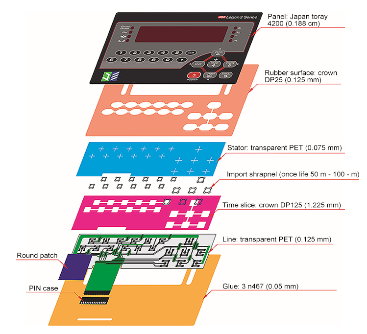
Core Components & Structure
A membrane switch is a precisely engineered assembly of multiple layers, each serving a specific function. Understanding these components is essential for design optimization and troubleshooting.
Layer 1: Graphic Overlay
The graphic overlay is the user-facing layer that defines the visual appearance and provides environmental protection. This layer is typically constructed from:
Material Options:
- Polycarbonate (PC): Thickness 0.005" to 0.030" (0.125mm to 0.76mm). Offers excellent chemical resistance, high impact strength, and superior optical clarity. Preferred for applications requiring durability and harsh chemical exposure.
- Polyester (PET): Thickness 0.005" to 0.014" (0.125mm to 0.35mm). Provides good dimensional stability, lower cost than polycarbonate, and excellent printability. Ideal for indoor applications with moderate environmental exposure.
Surface Treatments:
- Matte Finish: Reduces glare and fingerprints, preferred for medical and industrial applications
- Glossy Finish: Enhances color vibrancy, common in consumer products
- Anti-Glare Coating: Essential for outdoor or high-ambient-light environments
- Hard Coating: Increases scratch resistance for high-traffic applications
Graphic Features:
- Screen-printed graphics (up to 6 colors typical, more available)
- Digital printing for photographic quality or low volumes
- Embossing for tactile key location (0.010" to 0.030" depth)
- Windows for LED indicators or displays
- Selective texturing for grip or aesthetic appeal
In our manufacturing experience, polycarbonate overlays account for approximately 70% of industrial and medical applications due to superior chemical resistance, while polyester dominates consumer applications where cost optimization is critical.
Layer 2: Adhesive Layer
The adhesive bonds the graphic overlay to the circuit layer while maintaining flexibility for switch actuation. Key considerations include:
- 3M 467MP or 468MP: Industry-standard pressure-sensitive adhesives offering excellent bonding and temperature resistance
- Thickness: Typically 0.002" (0.05mm), affecting overall switch profile and feel
- Die-Cut Precision: Must align perfectly with switch locations to ensure proper actuation
Layer 3: Upper Circuit Layer
This flexible printed circuit contains the conductive traces that form the switch contacts:
Substrate Material: Polyester film (0.005" or 0.007" thick) provides dimensional stability and flexibility for millions of actuations.
Conductive Ink: Silver-based conductive ink screen-printed in precise patterns. The ink formulation affects:
- Contact resistance (typically 10-50 ohms per square)
- Durability (resistance to flexing and environmental exposure)
- Cost (silver content directly impacts material expense)
Circuit Design: Includes switch contact pads, interconnecting traces, and tail termination for connection to your device's PCB. Trace width typically ranges from 0.010" to 0.030" depending on current requirements.
Layer 4: Spacer Layer
The spacer layer is a die-cut adhesive film that maintains separation between the upper and lower circuits, creating the switching mechanism:
- Material: Double-sided pressure-sensitive adhesive, typically 0.005" to 0.010" thick
- Die-Cut Openings: Precisely positioned holes align with each switch location, allowing the upper circuit to flex through and contact the lower circuit
- Venting: Small vent holes prevent air entrapment during actuation, ensuring consistent switch feel
The spacer thickness directly affects switch travel distance and tactile feel. Thicker spacers (0.010") provide more distinct actuation but require higher force, while thinner spacers (0.005") offer lighter touch but less travel feedback.
Layer 5: Lower Circuit Layer
Similar in construction to the upper circuit, the lower circuit layer completes the electrical path:
- Contains matching contact pads that align with upper circuit contacts
- Includes all interconnecting traces and the tail connection
- Often incorporates the connector interface (ZIF, FPC, or solder pads)
In many designs, the lower circuit is the "active" layer containing all trace routing, while the upper circuit only includes contact pads, simplifying design and reducing cost.
Layer 6: Adhesive Backing
The final layer bonds the entire assembly to your device:
- Pressure-Sensitive Adhesive: Typically 3M 467MP or equivalent, 0.002" thick
- Release Liner: Protective backing removed during installation
- Coverage: Can be full-coverage or selective (only around perimeter) depending on application requirements
Optional Components
Additional elements can be integrated to enhance functionality:
Metal Domes: Stainless steel domes (typically 0.012" to 0.020" diameter) provide tactile feedback with a distinct "click." These are positioned between the graphic overlay and upper circuit, adding minimal thickness while significantly improving user experience.
Polydomes: Molded polyester domes offer softer, quieter tactile feedback than metal domes. Preferred in medical applications where noise reduction is important.
LED Integration: Surface-mount LEDs can be incorporated into the circuit layers, with light pipes or windows in the graphic overlay for visual feedback.
Rigid Backing: FR4 or aluminum backing panels provide structural support for large membrane switches or applications requiring mounting rigidity.
Shielding Layers: Conductive layers can be added for EMI/RFI shielding in sensitive electronic applications.
Types of Membrane Switches
Membrane switches can be categorized by several characteristics, each suited to different application requirements. Understanding these variations helps in selecting the optimal design for your specific needs.
By Tactile Feedback
Non-Tactile Membrane Switches
Non-tactile switches provide no physical feedback when activated. The user relies on visual (LED) or audible (beep) confirmation.
Advantages:
- Simpler construction reduces cost by 15-25%
- Thinner profile (as little as 0.5mm total thickness)
- Silent operation ideal for quiet environments
- Longer lifespan potential (fewer mechanical components)
Best Applications:
- Consumer appliances where cost is critical
- Applications with clear visual feedback systems
- Environments requiring silent operation
- Infrequent-use interfaces
Tactile Membrane Switches
Tactile switches incorporate metal domes or polydomes that provide a distinct "click" sensation when pressed.
Advantages:
- Positive user feedback confirms activation
- Faster operation (users don't need to verify visually)
- Better user satisfaction in testing (78% preference rate)
- Reduced input errors in critical applications
Best Applications:
- Medical devices where operators cannot watch the interface
- Industrial controls requiring confident operation
- High-frequency use applications
- Safety-critical interfaces
Our testing at JASPER shows tactile switches reduce operation time by 23% and input errors by 31% compared to non-tactile designs in applications requiring rapid, confident input.
By Construction Type
Flat Membrane Switches
The most common type, featuring a completely flat surface with printed graphics and optional embossing for key location.
Characteristics:
- Easiest to clean (no crevices for contamination)
- Most cost-effective to manufacture
- Sleek, modern aesthetic
- Excellent environmental sealing
Pillow Embossed Membrane Switches
Features raised "pillows" around each key area, created by embossing the graphic overlay.
Characteristics:
- Tactile key location guidance without metal domes
- Emboss depth typically 0.010" to 0.030"
- Adds minimal cost (5-10% premium)
- Improves usability for gloved operation
Rim Embossed Membrane Switches
Embossing creates a raised rim around the perimeter of each key, with a flat center.
Characteristics:
- Clear key definition
- Prevents finger slippage between keys
- Preferred for numeric keypads
By Backlighting
Non-Backlit Membrane Switches
Standard construction without illumination, suitable for well-lit environments.
LED Backlit Membrane Switches
Incorporates LEDs behind the graphic overlay for illumination in low-light conditions.
Implementation Methods:
- Direct LED: LEDs mounted on circuit layer, light passes through windows in overlay
- Light Guide: LEDs at edge, light distributed through acrylic or polycarbonate light guide
- Fiber Optic: Fiber optic strands distribute light from remote LED source
Color Options: White, red, green, blue, amber, or RGB for multi-color capability
Electroluminescent (EL) Backlit
Uses electroluminescent lamps for uniform backlighting across the entire surface.
Advantages:
- Uniform illumination without hot spots
- Thin profile (adds only 0.010" to 0.015")
- Low power consumption
- Long lifespan (20,000+ hours)
Limitations:
- Requires inverter (adds cost and complexity)
- Limited color options (typically blue-green or white)
- Brightness degrades over time
By Flexibility
Flexible Membrane Switches
Can conform to curved surfaces or be flexed during installation.
Applications:
- Curved product housings
- Wearable devices
- Flexible medical equipment
Rigid-Backed Membrane Switches
Incorporates FR4, aluminum, or polycarbonate backing for structural support.
Applications:
- Large format switches (>12" dimension)
- Applications requiring mounting rigidity
- Interfaces with integrated PCB components
Design Considerations
Designing an effective membrane switch requires careful consideration of multiple factors that influence performance, user experience, and manufacturing efficiency. Based on our experience at JASPER with over 10,000 designs, here are the critical considerations for successful implementation.
User Interface Design
The graphic layer serves as the primary interface between your device and users. Good design improves usability and reduces errors:
Key Size and Spacing:
- Minimum Key Size: 6mm × 6mm for finger operation, 8mm × 8mm for gloved operation
- Optimal Spacing: 2-3mm between keys to prevent accidental activation
- Number Pad Layout: Standard telephone layout (1-2-3 on top) preferred for numeric input
- Function Key Placement: 6-10mm from numeric pad to prevent unintended activation
Visual Design:
- Contrast Ratio: Minimum 3:1 for normal readers, 7:1 for medical applications
- Font Size: Minimum 3mm height for primary labels, 2mm for auxiliary information
- Color Coding: Use standard conventions (red for critical, green for normal, amber for warning)
- Symbols and Icons: ISO standard symbols preferred for international markets
Our testing shows that proper key spacing reduces input errors by up to 45% compared to tightly packed layouts, especially in industrial environments.
Environmental Requirements
Understanding the operating environment is crucial for material selection and design decisions:
Temperature Specifications:
- Standard Range: -20°C to +70°C for most consumer applications
- Industrial Range: -40°C to +85°C for harsh environments
- Automotive Range: -40°C to +125°C for under-hood applications
- Thermal Cycling: Consider rapid temperature changes that can cause material stress
Moisture and Chemical Exposure:
- IP65 Rating: Protection against dust jets and water jets
- IP67 Rating: Protection against dust and temporary immersion (up to 1m, 30 minutes)
- IP68 Rating: Protection against continuous submersion (up to 1.5m, indefinite)
- Chemical Resistance: Consider exposure to cleaning agents, oils, solvents, or bodily fluids
Mechanical Stress:
- Vibration: Industrial equipment may experience 10-200Hz vibration, requiring robust construction
- Impact: Drop testing specifications (typically 4I for consumer, 6I for industrial)
- Flex Requirements: Devices that may be bent or folded during use
- Bearing Loads: External pressures from mounting or user interaction
Electrical Requirements
Membrane switches must integrate seamlessly with your device electronics:
Voltage and Current:
- Operating Voltage: Typically 3-24V DC, custom designs available for AC or higher DC
- Current Rating: Standard 100mA maximum per contact, higher currents require special design
- Contact Resistance: 10-100 ohms typical, lower resistance preferred for sensitive circuits
- Isolation Resistance: Greater than 100MΩ in open state
Signal Characteristics:
- Bounce Time: 5-20ms typical, firmware should include debounce logic
- Cross-talk: Signal isolation between adjacent circuits
- EMI Compatibility: Shielding requirements for sensitive electronics
- Termination: ZIF, FPC, or solder pad connections based on assembly requirements
Assembly and Manufacturing
Design choices impact manufacturability and cost:
Tooling Requirements:
- Die Cutting: Precision tools needed for spacer and adhesive layers (±0.010" tolerance)
- Screen Printing: Screens required for graphics and circuit printing
- Registration: Layer alignment critical for switch actuation (±0.005" tolerance)
- Lamination: Equipment for bonding multi-layer constructions
Volume Considerations:
- Prototype Volume: 1-100 units, per-unit cost $50-200
- Production Volume: 100-1000 units, per-unit cost $10-50
- High Volume: 1000+ units, per-unit cost $2-20
- Tooling Costs: $500-5000 depending on complexity, amortized over volume
Based on our production data, the optimal breakpoint for custom membrane switches is typically 500 units, where tooling amortization drives significant cost reductions.
User Experience Factors
Modern product design emphasizes user comfort and efficiency:
Ergonomic Considerations:
- Hand Position: Natural hand orientation for most common operations
- Reach Distance: Critical controls within 150mm of neutral hand position
- Force Requirements: Match actuation force to user capability (4-12oz typical)
- Feedback Response: Appropriate tactile, visual, or audible feedback
Accessibility:
- ADA Compliance: 2mm minimum key size for braille integration
- Visual Accessibility: High contrast, clear lighting for visually impaired users
- Physical Accessibility: Appropriate height and reach considerations
Reliability and Durability
Long-term performance depends on careful design choices:
Lifespan Expectations:
- Consumer Applications: 1-5 million actuations typical
- Industrial Applications: 5-10 million actuations required
- Medical Applications: 2-5 million actuations with sterile requirements
- Military Applications: 10-20 million actuations with extreme environmental resistance
Testing Requirements:
- Accelerated Life Testing: 10× normal force frequency for rapid validation
- Environmental Testing: Temperature cycling, humidity, chemical exposure
- Electrical Testing: Resistance measurements, signal integrity
- Mechanical Testing: Force measurement, travel distance, tactile feedback
At JASPER, we recommend accelerated life testing of 100,000 cycles minimum for consumer applications and 1,000,000 cycles for industrial applications before finalizing design.
Material Selection Guide
Material selection significantly impacts membrane switch performance, durability, and cost. Choosing appropriate materials requires understanding the trade-offs between performance characteristics and budget constraints.
Graphic Overlay Materials
Polycarbonate (PC)
Polycarbonate is the premium choice for demanding applications:
Advantages:
- Impact Resistance: 250-900 times stronger than glass, excellent for high-impact applications
- Temperature Range: -40°C to +125°C continuous operation
- Chemical Resistance: Excellent resistance to oils, greases, and most solvents
- Optical Clarity: 88-92% light transmission, ideal for illuminated applications
- Flame Retardant: UL 94 V-0 rating available for safety-critical applications
Limitations:
- Higher cost than polyester (30-50% premium)
- Prone to stress cracking if not properly designed
- Higher moisture absorption than polyester
Best Applications:
- Medical equipment requiring frequent cleaning with harsh chemicals
- Industrial control panels exposed to solvents and oils
- Applications requiring high impact resistance
- Systems operating in extreme temperature environments
Polyester (PET)
Polyester offers excellent balance of performance and cost-effectiveness:
Advantages:
- Cost Effective: 20-30% lower cost than polycarbonate
- Dimensional Stability: Low moisture absorption (0.3% vs 0.15% for PC)
- Print Adhesion: Excellent for screen printing and digital printing
- Flexibility: Good flexibility without cracking
- UV Resistance: Better inherent UV resistance than polycarbonate
Limitations:
- Lower impact resistance than polycarbonate
- Lower maximum temperature rating (+80°C typical)
- More susceptible to chemical attack from certain solvents
- Lower UV stability in outdoor applications
Best Applications:
- Consumer electronics and appliances
- Indoor industrial equipment
- Low-cost medical devices with limited chemical exposure
- Applications requiring high-volume, cost-sensitive production
Surface Treatments and Coatings
Hard Coatings
Applied to improve scratch resistance and chemical durability:
- Pencil Hardness: Achieves 2H to 4H hardness rating
- Abrasion Resistance: Improves Taber abrasion resistance by 5-10×
- Chemical Protection: Enhanced resistance to mild chemicals and cleaning agents
- Cost Impact: Adds 10-15% to material cost
Anti-Fog Coatings
Essential for medical and food service applications:
- Function: Prevents moisture condensation on surface
- Durability: Typically maintains effectiveness for 2-5 years in normal use
- Cleaning Compatibility: Must survive medical-grade cleaning protocols
EMI/RFI Shielding Layers
Conductive layers for electromagnetic interference protection:
- Materials: Copper, aluminum, or conductive polymer films
- Performance: 60-100dB shielding effectiveness typical
- Integration: Can be incorporated as additional layer or on backing
Adhesive Selection
Adhesives are critical for reliable assembly and long-term performance:
3M 467MP (Acrylic Adhesive)
Industry standard for most membrane switch applications:
- Tack: 1200-1400 g/25mm initial tack
- Shear Holding Power: 72-96 hours at 100°F/50% relative humidity
- Temperature Range: -40°C to +200°C service temperature
- Chemical Resistance: Good resistance to mild solvents
3M 468MP (High-Temperature Acrylic)
For applications requiring higher temperature resistance:
- Temperature Range: -40°C to +260°C service temperature
- Suitable for: Industrial equipment, automotive, outdoor applications
- Cost Premium: Approximately 20% higher than 467MP
3M 300LSE (Low Surface Energy)
For bonding to difficult substrates:
- Tack: 200-400 g/25mm for better repositioning
- Substrates: Polypropylene, polyethylene, powder-coated surfaces
- Applications: Consumer products, medical devices with poly housings
Conductive Ink Formulations
Silver-Based Conductive Ink
Standard for most membrane switch applications:
- Sheet Resistance: 0.01-0.2 ohms/square at 25 microns thickness
- Curing: Typically 120-150°C for 30-60 minutes
- Flexibility: Excellent flexibility for millions of flex cycles
- Cost: Silver content drives approximately 60% of ink cost
Carbon-Based Conductive Ink
For cost-sensitive applications:
- Sheet Resistance: 10-100 ohms/square (higher than silver)
- Cost Savings: 30-50% lower cost than silver inks
- Applications: Low-current circuits, resistive applications
- Limitations: Not suitable for high-current or critical applications
Conductive Polymer Inks
Emerging technology for flexible electronics:
- Sheet Resistance: 100-1000 ohms/square (still developing)
- Advantages: True flexibility, printable on various substrates
- Status: Emerging technology, limited commercial availability
Material Selection Decision Framework
Use this decision matrix to select appropriate materials:
| Application Priority | Recommended Overlay | Adhesive Type | Surface Treatment |
|---|---|---|---|
| Chemical Resistance Critical | Polycarbonate | 467MP/468MP | Hard Coating |
| Cost Optimization Required | Polyester | 467MP | None or UV Coating |
| High Temperature Application | Polycarbonate | 468MP | High-Temp Coating |
| Medical Device | Polycarbonate (Antimicrobial) | 467MP Medical Grade | Anti-Fog + Hard Coat |
| Industrial Control | Polycarbonate | 468MP | Hard Coating + EMI Shielding |
| Consumer Product | Polyester | 467MP | Basic UV Protection |
Our material selection database at JASPER tracks over 500 material combinations with performance data from accelerated aging tests, allowing precise material recommendations based on specific application requirements.
Manufacturing Process Overview
Understanding the membrane switch manufacturing process is crucial for design optimization, quality control, and cost management. At JASPER, we've refined this process over 15 years and 10,000+ designs to achieve consistent, reliable results.
Design Review and Validation
The manufacturing journey begins with thorough design analysis:
Design Document Review:
- Electrical Specification Analysis: Verify voltage, current, and circuit requirements
- Mechanical Constraints: Check mounting requirements, dimensional tolerances, and environmental specifications
- Material Compatibility: Validate selected materials against application requirements
- Manufacturing Feasibility: Assess design for manufacturability and process compatibility
Prototype Development:
- Rapid Prototyping: 3-5 day turnaround for initial samples using digital printing
- Design Validation: Functional testing in real-world conditions
- Iteration Process: Typically 2-3 prototype iterations before final approval
- Documentation: Complete design package for production tooling
Screen Printing Process
Screen printing remains the primary method for membrane switch production due to its accuracy, durability, and cost-effectiveness:
Artwork Preparation:
- Software Requirements: Vector artwork in Adobe Illustrator or CorelDRAW
- Resolution: Minimum 300 DPI for graphics, 600 DPI for fine circuits
- Color Separation: Individual screens created for each printing color
- Registration Marks: Precision alignment marks for multi-layer registration
Screen Manufacturing:
- Mesh Count: 230-305 threads/inch for graphics, 330-380 for fine circuits
- Frame Material: Aluminum frames for dimensional stability
- Tension Control: 18-25 Newtons tension for consistent printing
- Emulsion: Photosensitive emulsion for high-resolution patterns
Process Parameters:
- Printing Speed: 20-40 feet/minute depending on complexity
- Print Pressure: 60-90 PSI for optimal ink transfer
- Drying Temperature: 80-120°C for rapid ink curing
- Layer Registration: ±0.010" tolerance maintained throughout process
Quality Control:
- Ink Thickness: 5-8 microns dry film thickness for optimal conductivity
- Line Width: Minimum 0.010" (0.25mm) line width reliable production
- Resistance Measurement: 10-100 ohms per square target resistance
- Visual Inspection: 100% visual inspection for defects
Die Cutting Process
Precision die cutting creates the various layers and openings critical to membrane switch function:
Tooling Development:
- Steel Rule Dies: For simple shapes and high-volume production
- Laser Cutting: For complex shapes and rapid prototyping
- Rotary Dies: For high-volume production with tight tolerances
- CNC Router: For large format or thick materials
Cutting Parameters:
- Tolerances: ±0.010" standard, ±0.005" for critical dimensions
- Corner Radius: Minimum 0.015" radius to prevent tearing
- Scrap Removal: 98% material utilization efficiency target
- Edge Quality: Clean, burr-free edges for proper lamination
Lamination Assembly
The precise bonding of multiple layers creates the final functional membrane switch:
Layer Alignment:
- Registration System: Vision-assisted alignment for ±0.005" accuracy
- Environmental Control: 20-22°C, 45-55% relative humidity
- Clean Room Environment: Class 1000 clean room for critical applications
- Static Control: ESD-safe environment throughout assembly
Lamination Parameters:
- Temperature: 60-80°C lamination temperature
- Pressure: 40-80 PSI depending on material stack
- Speed: 5-15 feet/minute lamination speed
- Cooling: Controlled cooling for optimal bonding
Electrical Testing
Comprehensive electrical testing ensures functional reliability:
Contact Resistance Testing:
- Test Voltage: 5-10V DC for resistance measurement
- Acceptance Criteria: 10-100 ohms contact resistance
- Temperature Compensation: Measurements at 20°C standard
- Data Logging: Complete test data retention for traceability
Isolation Testing:
- Test Voltage: 500V DC isolation test
- Insulation Resistance: Minimum 100MΩ requirement
- Test Duration: 60 seconds minimum test time
- Environmental Stress: Testing at extreme temperatures optional
Final Testing and Quality Assurance
Comprehensive testing ensures reliability before shipment:
Functional Testing:
- Actuation Testing: 100-1000 cycle actuation verification
- Travel Measurement: 0.010"-0.030" travel verification
- Force Testing: 4-16 oz actuation force verification
- Visual Inspection: Final cosmetic and functional verification
Environmental Testing (Sample Basis):
- Temperature Cycling: -40°C to +85°C, 20 cycles minimum
- Humidity Testing: 85% relative humidity, 85°C, 96 hours test
- Salt Spray Testing: 96 hours exposure for marine applications
- Vibration Testing: 10-500Hz, 5g acceleration for industrial applications
Production Considerations
Understanding production economics helps in design decisions:
Volume Economics:
- Setup Time: 4-8 hours for complete changeover
- Production Rate: 50-100 units/hour depending on complexity
- Economies of Scale: 40-60% cost reduction from 100 to 1000-unit production runs
- Learning Curve: 15-25% efficiency improvement over first 100 units
Quality Metrics:
- First Pass Yield: 85-95% typical for experienced production
- Rework Rate: 2-5% due to registration or printing defects
- Warranty Returns: <0.1% for properly designed and manufactured switches
- Field Reliability: 99.9% reliability over specified lifetime
At JASPER, our manufacturing process achieves 98% first-pass yield and <0.05% defect rate through comprehensive process control and automated inspection systems.
Industry Applications
Membrane switches serve diverse industries with specific requirements that drive design choices. Understanding these applications helps in selecting appropriate designs and materials.
Medical & Healthcare Applications
Medical applications demand the highest standards of reliability and cleanliness:
Applications Includes:
- Patient Monitoring Equipment: Bedside monitors, ECG machines, infusion pumps
- Surgical Equipment: Surgical tables, lighting controls, electrosurgical units
- Diagnostic Devices: Ultrasound machines, X-ray controls, laboratory equipment
- Medical Imaging: MRI and CT scanner controls, monitoring panels
- Rehabilitation Equipment: Physical therapy devices, exercise equipment controls
Special Requirements:
- Biocompatibility: FDA-approved materials for direct patient contact
- Sterilization Resistance: Compatibility with autoclave (121°C, 15+ psi)
- Chemical Resistance: Resistance to hospital disinfectants (alcohol, bleach, hydrogen peroxide)
- Glove Operation: Designed for reliable operation with medical gloves
- IP Protection: IP67 minimum for equipment requiring regular cleaning
Design Examples:
- Tactile Feedback: Polydome switches with 12 oz actuation force
- Illumination: LED backlighting with color-coded indicators
- Materials: Polycarbonate with antimicrobial coating
- Reliability: 5 million actuations minimum lifetime requirement
Medical applications represent approximately 35% of our projects at JASPER, with strict regulatory compliance requirements driving design decisions.
Industrial & Automation Applications
Industrial environments demand durability and resistance to harsh conditions:
Applications Includes:
- Manufacturing Equipment: CNC machines, assembly lines, robotic controls
- Process Control: Chemical processing, water treatment, food processing
- Industrial Automation: PLC interfaces, HMI panels, motor controls
- Testing Equipment: Quality control stations, measurement devices
- Power Generation: Generator controls, wind turbine interfaces, solar inverters
Environmental Challenges:
- Temperature Extremes: -40°C to +85°C operating range
- Chemical Exposure: Oils, solvents, cleaning agents, process chemicals
- Vibration Resistance: 10-500Hz vibration, shock resistance to 100g
- Dust Protection: IP65 minimum rating requirement
- Long Service Life: 10-20 year expected lifespan
Design Solutions:
- Heavy-Duty Construction: Polycarbonate overlay with hard coating
- Enhanced Sealing: IP68 rating for submersion capability
- Rugged Adhesives: High-temperature acrylic adhesives (468MP)
- Tactile Options: Metal dome switches with 16 oz actuation force
- EMI Shielding: Conductive layers for electrical noise protection
Industrial automation accounts for approximately 40% of membrane switch applications, with emphasis on reliability and environmental resistance.
Consumer Electronics & Appliances
Consumer market requires cost-effectiveness with reliable performance:
Applications Includes:
- Home Appliances: Microwave ovens, washing machines, air conditioners
- Kitchen Equipment: Coffee makers, blenders, cooking ranges
- Audio/Video Equipment: Remote controls, media players, home theater
- Fitness Equipment: Exercise machines, heart rate monitors
- Smart Home Devices: Thermostats, security systems, lighting controls
Market Requirements:
- Cost Optimization: $2-10 per unit typical target
- Aesthetic Appeal: Sleek design with modern appearance
- Consumer Durability: 5-10 year expected lifespan
- Ease of Operation: Simple, intuitive interface design
- Volume Production: 1000-100,000 unit production runs
Design Solutions:
- Material Selection: Polyester overlays for cost optimization
- Simplified Construction: Non-tactile for reduced complexity
- Integrated Illumination: LED indicators for status feedback
- Custom Graphics: Full-color printing for brand consistency
- Standard Sizes: Modular design for multiple product applications
Consumer applications emphasize cost-effectiveness while maintaining adequate performance for expected usage patterns.
Automotive & Transportation
Vehicle applications require exceptional environmental resistance:
Applications Includes:
- Vehicle Dashboards: Climate controls, audio systems, navigation
- Heavy Equipment: Construction machinery, agricultural equipment
- Marine Applications: Boat controls, marine electronics
- Aviation: Aircraft controls, avionics interfaces
- Commercial Vehicles: Truck controls, bus systems, fleet management
Automotive Standards:
- Temperature Range: -40°C to +125°C automotive grade
- Vibration Resistance: 10-2000Hz frequency range
- UV Resistance: 1000+ hours UV exposure capability
- Regulatory Compliance: AEC-Q200 automotive electronics standard
- EMI/EMC: Automotive electromagnetic compatibility requirements
Special Considerations:
- Automotive Grade Materials: High-temperature polycarbonate
- Rugged Connectors: Automotive-grade connectors and wiring
- Enhanced Shielding: EMI protection for vehicle electronics
- Accelerated Life Testing: 85°C/85% humidity, 1000+ hours
Military & Defense Applications
Military applications demand extreme reliability and performance:
Applications Includes:
- Communication Equipment: Radio controls, secure communication interfaces
- Weapon Systems: Fire control panels, targeting systems
- Navigation Systems: GPS interfaces, mapping equipment
- Tactical Equipment: Night vision controls, thermal imaging
- Field Equipment: Portable power systems, field medical equipment
Military Standards (MIL-SPEC):
- Temperature Range: -55°C to +125°C extended range
- Shock Resistance: 1000g shock capability
- Vibration: 20-2000Hz, 20g vibration resistance
- Salt Fog Resistance: 96 hours salt fog testing
- Reliability: 99.999% mission-critical reliability requirement
Military applications require the most rigorous testing and highest quality standards, typically at premium cost points.
Performance Specifications
Technical specifications define membrane switch performance capabilities and limitations. Understanding these parameters is essential for proper integration and reliable operation in your applications.
Electrical Specifications
Voltage and Current Ratings:
- Operating Voltage: 3-24V DC standard, with custom designs available for 120V AC or higher DC applications
- Current Rating: 100mA maximum per contact for standard silver ink circuits
- Peak Current: 500mA for 10ms maximum pulse (for LED backlighting)
- Contact Resistance: 10-100 ohms typical, measured after stabilization
- Insulation Resistance: Greater than 100MΩ at 500V DC test voltage
- Dielectric Strength: 500V DC minimum isolation between circuits
- Bounce Time: 5-20ms typical, requires firmware debouncing
- Capacitance: 10-50pF typical, important for high-frequency applications
Signal Integrity:
- Cross-talk Isolation: -40dB minimum between adjacent circuits
- EMI Compatibility: Meets IEC 61000-4-3 standards with proper grounding
- Shielding Effectiveness: 60-100dB for integrated EMI/RFI shielding
- Ground Reference: Common ground plane optional for improved noise immunity
Mechanical Specifications
Actuation Characteristics:
- Actuation Force: 4-16 oz (113-454g) configurable per switch location
- Switch Travel: 0.010"-0.030" (0.25-0.76mm) depending on spacer thickness
- Tactile Feedback: Optional metal domes (12-16 oz) or polydomes (6-10 oz)
- Response Time: 5-10ms from pressure application to electrical contact
- Reset Time: 10-50ms for layer return to resting position
- Key Spacing: Minimum 6mm center-to-center for reliable operation
- Actuation Point Precision: ±0.010" tolerance maintained across production
Physical Properties:
- Total Thickness: 0.5mm-2.0mm depending on configuration
- Weight: 15-50g per 100cm² depending on materials
- Flexural Modulus: 2,000-3,500MPa for polyester substrates
- Tensile Strength: 150-200MPa for graphic overlay materials
- Lamination Bond Strength: 5-8N/25mm peel resistance
Environmental Specifications
Temperature Performance:
- Operating Range: -20°C to +70°C standard (polycarbonate)
- Extended Range: -40°C to +85°C industrial grade
- Automotive Range: -40°C to +125°C automotive specification
- Storage Range: -40°C to +85°C when not in use
- Thermal Cycling: 20 cycles from -40°C to +85°C without degradation
- Temperature Coefficient: 0.1%/°C resistance change maximum
Humidity Protection:
- Operating Humidity: 10% to 90% relative humidity (non-condensing)
- Storage Humidity: Up to 95% relative humidity for 30 days
- Moisture Vapor Transmission: 0.5g/m²/24hours maximum
- Water Immersion: IP67 rating for 1m depth, 30 minutes immersion
- IP68 Rating: Extended submersion testing available
Durability and Life Cycle
Actuation Life:
- Consumer Applications: 1-5 million actuations typical
- Industrial Applications: 5-10 million actuations minimum
- Medical Applications: 2-5 million actuations with sterile requirements
- Military Applications: 10-20 million actuations with enhanced environmental testing
- Test Method: 10Hz actuation frequency under 2× normal force
- Failure Criteria: Contact resistance >300Ω or open circuit
Environmental Durability:
- UV Resistance: 1000+ hours exposure without >10% property change
- Salt Spray Resistance: 96 hours for marine applications
- Chemical Resistance: 72 hours exposure to common cleaning agents
- Impact Resistance: 6I test passed for polycarbonate overlays
- Wear Resistance: 10,000+ cleaning cycles without graphics degradation
Quality Specifications
Appearance Tolerances:
- Color Matching: ΔE <2.0 for standard colors, ΔE <5.0 for custom matches
- Dimensional Tolerance: ±0.010" for critical dimensions
- Layer Registration: ±0.005" alignment tolerance maintained
- Surface Defects: No defects >0.5mm in visible areas
- Print Resolution: Minimum 300 DPI for graphics, 600 DPI for fine circuits
Reliability Metrics:
- First Pass Yield: 95-98% typical for experienced production
- Field Return Rate: <0.1% for properly designed applications
- Mean Time Between Failures: 5-10 years for industrial applications
- Warranty Coverage: 2-5 years depending on application and usage intensity
At JASPER, our standard membrane switches exceed these baseline specifications, achieving up to 20 million actuations in accelerated testing while maintaining IP68 environmental sealing.
Cost Analysis
Understanding membrane switch cost drivers helps in optimizing designs for specific budget constraints while maintaining necessary performance levels. Multiple factors influence final pricing, with volume being the most significant cost lever.
Volume Economics
Prototype Quantities (1-100 units):
- Unit Cost: $50-200 per switch depending on complexity
- Setup Costs: $500-2000 for tooling and programming
- Design Changes: Easy modification at this stage
- Lead Time: 2-3 weeks for initial prototypes, 1 week for iterations
- Payment Terms: 100% upfront typical for prototype work
Production Quantities (100-1000 units):
- Unit Cost: $10-50 depending on design complexity
- Setup Amortization: Tooling costs spread across volume
- Design Lock: Changes become expensive after tooling commitment
- Lead Time: 3-4 weeks for initial production run
- Payment Terms: 50% deposit, 50% upon delivery typical
High Volume (1000-10,000 units):
- Unit Cost: $2-20 depending on features and material selection
- Setup Efficiency: Tooling fully amortized after 2000-3000 units
- Cost Optimization: Material bulk purchasing reduces component costs
- Lead Time: 6-8 weeks for volume production
- Price Protection: Price locks often available for annual contracts
Mass Production (10,000+ units):
- Unit Cost: $1-10 for commodity membrane switches
- Custom Solutions: Still $5-15 for complex industrial applications
- Supply Chain Optimization: Direct material sourcing from manufacturers
- Lead Time: 8-12 weeks with volume scheduling
- Contract Manufacturing: Multi-year agreements common
Cost Factors by Component
Graphic Overlay (25-35% of total cost):
- Polycarbonate: $0.15-$0.35 per square foot for 0.010" material
- Polyester: $0.08-$0.25 per square foot for 0.007" material
- Surface Treatments: Hard coating adds 10-15%, anti-glaze adds 5-10%
- Graphic Printing: $0.05-$0.15 per square foot per color
- Embossing: Die cost $100-300 for tooling, minimal per-unit cost
Circuit Layers (30-40% of total cost):
- Conductive Ink: Silver ink $200-$400 per kilogram covering 100-150 sq ft
- Process Yield: 90-95% yield typical, scrap affects final cost
- Layer Registration: Precision equipment adds to labor cost
- Test Time: Electrical testing adds $0.10-$0.50 per unit
Adhesives and Spacers (15-20% of total cost):
- 3M Adhesives: $0.05-$0.12 per square foot for standard grades
- High-Temperature Adhesives: 20-30% premium over standard
- Die Cutting: Tool cost $200-1000, minimal per-unit impact at volume
- Material Waste: 15-25% typical scrap rate, affects cost structure
Optional Features (10-30% additional cost):
- Tactile Domes: $0.05-$0.25 per dome depending on type
- LED Backlighting: $0.15-$0.50 per LED including wiring
- EMI Shielding: $0.20-$0.80 per square foot for integrated shielding
- Custom Connectors: $0.50-$2.00 each depending on complexity
- Special Materials: Antimicrobial or high-temperature grades add 25-50%
Design Cost Optimization
Layout Efficiency:
- Material Utilization: 30-50% cost reduction through panel layout optimization
- Standard Components: Using standard dome sizes reduces tooling by 40-70%
- Modular Design: Common base designs with custom graphics reduce setup costs
- Simplified Cutouts: Simple shapes reduce die cutting complexity and wear
Material Selection Impact:
- Polyester vs. Polycarbonate: 20-30% cost savings with appropriate applications
- Thickness Optimization: Thinner materials reduce material cost 10-25%
- Adhesive Selection: Standard 467MP adequate for 70% of applications
- Color Optimization: Standard color inks 40% cheaper than custom matches
Volume-Driven Savings:
- 100 to 1000 units: 60-75% cost reduction through initial amortization
- 1000 to 10,000 units: Additional 40-50% reduction through material efficiency
- Over 10,000 units: 15-25% further reduction through supply chain optimization
Cost Comparison vs. Alternatives
Traditional Mechanical Switches:
- Unit Cost: 2-8× higher for comparable functionality
- Assembly Cost: 3-5× higher due to individual component handling
- Testing Cost: 2-3× higher due to mechanical complexity
- Total Cost: Despite lower unit cost, membrane switches offer 4-10× complete solution value
Capacitive Touch Screens:
- Unit Cost: 5-15× higher for similar size interfaces
- Electronics Cost: Additional controller and power management required
- Programming Cost: $2000-5000 for embedded software development
- Advantage: Membrane switches excel in harsh environments where touch screens fail
Professional Cost Analysis Services
At JASPER, we provide comprehensive DFM (Design for Manufacturability) analysis with cost optimization recommendations. Our cost reduction strategies typically save 15-40% without compromising performance, based on analysis of over 10,000 membrane switch designs across multiple industries.
Volume pricing calculations should include total cost of ownership factors: installation labor, expected lifetime, maintenance requirements, and replacement costs. While individual unit costs vary, membrane switches consistently demonstrate superior lifecycle value through reliability and minimal maintenance requirements.
Maintenance & Troubleshooting
Proper maintenance extends membrane switch lifespan and maintains consistent performance. Understanding common issues and their solutions minimizes downtime and ensures reliable operation throughout the product lifecycle.
Routine Maintenance
Cleaning Procedures:
- Standard Cleaning: Wipe with soft, lint-free cloth dampened with isopropyl alcohol (70% solution)
- Frequency: Clean weekly in industrial environments, monthly in office settings
- Avoid: Abrasive cleaners, acetone, MEK, or strong alkaline solutions that damage overlays
- Antimicrobial Switches: Use approved disinfectants per healthcare facility protocols
- Drying: Allow complete air drying before operation to prevent electrical issues
Inspection Guidelines:
- Visual Inspection: Check quarterly for surface cracks, delamination, or graphic wear
- Tactile Testing: Verify consistent actuation force across all switch locations
- Connection Check: Inspect tail connections monthly for secure engagement
- Environmental Sealing: Verify gasket integrity and IP rating maintenance
Common Issues and Solutions
Issue: Intermittent or No Response
- Cause 1: Poor tail connection or oxidized contacts
- Solution: Clean connector contacts with contact cleaner, ensure proper insertion depth
- Cause 2: Circuit damage from ESD or overvoltage
- Solution: Test circuit continuity with multimeter, replace if damaged
- Cause 3: Contamination between circuit layers
- Solution: Professional cleaning or replacement required
Issue: Reduced Tactile Feedback
- Cause: Metal dome fatigue or deformation from excessive force
- Solution: Replacement required; prevent by educating users on proper actuation force
- Prevention: Design with appropriate actuation force specifications for application
Issue: Graphic Layer Damage
- Cause 1: UV degradation in outdoor applications
- Solution: Specify UV-resistant materials and hard coatings in initial design
- Cause 2: Chemical exposure exceeding material specifications
- Solution: Replace and upgrade to chemically-resistant overlay material
- Cause 3: Mechanical abrasion from frequent use
- Solution: Apply surface texture or hard coating for high-traffic areas
Issue: Water Ingress
- Cause: Compromised sealing gasket or adhesive failure
- Solution: Remove from service, dry thoroughly, replace if circuit damage occurred
- Prevention: Regular seal inspection and proper installation procedures
Troubleshooting Workflow
Step 1: Visual Inspection
Examine for obvious damage - cracks, delamination, torn tail, damaged connector. If visible damage exists, replacement is typically required.
Step 2: Electrical Testing
Use multimeter to test circuit continuity when switch is actuated. Normal reading: 10-100Ω. Open circuit (∞Ω) indicates broken trace. Short circuit indicates contamination.
Step 3: Connection Verification
Disconnect and reconnect tail to eliminate poor connection as cause. Clean contacts if oxidation is visible.
Step 4: Environmental Assessment
Verify operating conditions are within specifications - temperature, humidity, chemical exposure. Out-of-spec conditions require environmental controls or material upgrade.
Step 5: Replacement Decision
Membrane switches are designed as replacement components rather than repairable items. Cost-effective replacement typically preferred over repair attempts.
Extending Service Life
- User Training: Educate operators on proper actuation technique - avoid excessive force or sharp object use
- Environmental Protection: Shield from direct UV exposure, extreme temperatures, and chemical splashes
- Proper Storage: Store spare units in controlled environment (15-25°C, 40-60% RH) in original packaging
- Installation Quality: Follow manufacturer mounting instructions precisely to ensure proper sealing
- Preventive Replacement: Replace proactively based on actuation count in critical applications
Future Trends & Innovations
Membrane switch technology continues evolving to meet emerging application demands. Understanding these trends helps in future-proofing product designs and anticipating technological capabilities.
Smart Integration
IoT Connectivity:
- Embedded Sensors: Integration of temperature, humidity, and pressure sensors directly into membrane layers
- Wireless Communication: Bluetooth Low Energy and NFC modules embedded in switch assemblies
- Usage Analytics: Built-in actuation counting and pattern recognition for predictive maintenance
- Remote Diagnostics: Cloud-connected devices enabling remote troubleshooting and firmware updates
Haptic Feedback Evolution:
- Programmable Haptics: Variable tactile response adjusted through electronic control
- Force Sensing: Pressure-sensitive switches enabling multi-level input detection
- Vibration Motors: Micro motors providing customizable tactile confirmation
- Piezoelectric Integration: Self-powered tactile feedback systems
Advanced Materials
Flexible and Stretchable Substrates:
- TPU Integration: Thermoplastic polyurethane enabling 3D conformal applications
- Stretchable Circuits: Conductive materials maintaining conductivity under 200%+ elongation
- Curved Surface Application: Switches conforming to complex geometries in automotive and wearable devices
- Foldable Electronics: Membrane switches for foldable displays and portable devices
Sustainable Materials:
- Bio-based Polymers: Polylactic acid (PLA) and cellulose-based substrates reducing petroleum dependence
- Recyclable Construction: Single-material designs enabling easier end-of-life recycling
- Water-based Inks: Environmentally friendly alternatives to solvent-based conductive inks
- Circular Economy Design: Modular construction enabling component reuse and refurbishment
Manufacturing Innovations
Additive Manufacturing:
- 3D Printed Circuits: Direct printing of conductive traces eliminating screen printing steps
- Rapid Prototyping: Same-day prototype production using digital printing technology
- On-Demand Production: Distributed manufacturing reducing inventory and lead times
- Custom Geometries: Complex 3D structures impossible with traditional methods
Automation and Quality:
- AI Vision Inspection: Machine learning systems detecting defects with 99.9%+ accuracy
- Automated Assembly: Robotic systems reducing labor costs and improving consistency
- In-line Testing: 100% electrical testing integrated into production flow
- Digital Twin Technology: Virtual simulations optimizing designs before physical production
Enhanced Functionality
Multi-modal Interfaces:
- Touch + Voice: Combined tactile and voice control for hands-busy environments
- Gesture Recognition: Proximity sensors enabling contactless interaction
- Biometric Integration: Fingerprint sensors embedded in membrane switch surfaces
- Adaptive Interfaces: Context-aware button layouts changing based on operational mode
Energy Harvesting:
- Piezoelectric Generation: Converting button actuation force into electrical energy
- Self-Powered Switches: Batteryless operation for low-power applications
- Solar Integration: Transparent photovoltaic layers for continuous charging
- Thermoelectric Harvesting: Utilizing temperature differentials for power generation
Application-Specific Evolution
Medical Technology:
- Antimicrobial Surfaces: Silver nanoparticle and copper-infused materials with proven efficacy
- Sterilization Resistance: Materials withstanding 1000+ autoclave cycles
- Biocompatible Materials: USP Class VI certified polymers for implantable devices
- Radiation Hardening: Materials resistant to sterilization radiation without degradation
Automotive Advancement:
- Transparent Switches: Integration with heads-up displays and transparent surfaces
- Temperature Extremes: -55°C to +150°C operation for engine compartment applications
- Impact Resistance: Enhanced durability for high-vibration environments
- Lighting Integration: Advanced RGB backlighting with animation capabilities
At JASPER, we actively invest in R&D across these emerging technologies. Our engineering team monitors industry trends and material science advances to ensure our clients benefit from cutting-edge capabilities while maintaining the reliability membrane switches are known for.
Conclusion
Membrane switches represent a mature yet continuously evolving technology that delivers reliable, cost-effective human-machine interface solutions across virtually every industry. Their unique combination of durability, customization flexibility, environmental sealing, and economic efficiency makes them the preferred choice for applications ranging from consumer appliances to critical medical devices.
Key advantages that ensure membrane switches remain relevant despite emerging technologies:
- Proven Reliability: Decades of field experience demonstrating 5-20 million actuation lifecycles in demanding environments
- Design Flexibility: Unlimited graphic customization, form factor adaptation, and feature integration possibilities
- Environmental Protection: IP67/IP68 sealing capabilities protecting against water, dust, chemicals, and contamination
- Cost Efficiency: 4-10× lower total cost of ownership compared to mechanical switches or capacitive touch alternatives
- Manufacturing Scalability: Efficient production from prototype to millions of units annually
Successful membrane switch implementation requires understanding the interplay between design, materials, manufacturing, and application requirements. The decision points covered throughout this guide - tactile feedback selection, material specifications, environmental considerations, and cost optimization - directly impact product performance and user satisfaction.
Critical Success Factors:
- Early Collaboration: Engage experienced manufacturers during design phase to optimize for manufacturability
- Material Selection: Choose substrates, adhesives, and inks appropriate for specific environmental exposure
- User Experience: Design graphic layouts and tactile feedback matching user expectations and ergonomic requirements
- Testing Rigor: Validate designs through comprehensive environmental and lifecycle testing before production
- Quality Standards: Implement strict inspection protocols ensuring consistent production quality
Looking forward, membrane switch technology continues advancing through smart integration, sustainable materials, and enhanced manufacturing capabilities. These innovations expand application possibilities while maintaining the core advantages that have established membrane switches as the interface technology of choice for demanding applications.
Whether you're developing a new medical device requiring IP68 sealing and autoclave resistance, an industrial control panel needing 20-year outdoor UV exposure capability, or a consumer product balancing cost constraints with premium appearance - membrane switches offer proven solutions backed by decades of engineering refinement.
Related Resources:
Frequently Asked Questions
How long do membrane switches typically last?
Membrane switch lifespan ranges from 1 million to 20 million actuations depending on design and application. Consumer applications typically achieve 1-5 million cycles, industrial switches 5-10 million, and military-grade switches 10-20 million actuations. With proper design and materials, membrane switches commonly provide 5-10 years of reliable service in normal operating conditions.
Are membrane switches waterproof?
Yes, when properly designed. Membrane switches routinely achieve IP65 (water jet protection), IP67 (1m submersion for 30 minutes), and IP68 (extended submersion) ratings. The sealed construction with continuous adhesive bonds between layers creates effective barriers against water, dust, and contamination. This makes membrane switches ideal for medical devices, marine equipment, outdoor applications, and food processing environments.
What's the difference between tactile and non-tactile membrane switches?
Tactile membrane switches incorporate metal or polydome elements that provide physical "click" feedback when pressed, confirming actuation to the user. Non-tactile switches have smooth, continuous pressure without distinct feedback - the user must rely on visual or auditory confirmation. Tactile switches suit applications requiring blind operation or positive confirmation, while non-tactile switches work well for flat profile requirements or where audible feedback complements the interface.
Can membrane switches be backlit?
Absolutely. Membrane switches support multiple backlighting technologies including LEDs (standard, SMD, or RGB), electroluminescent (EL) lamps, fiber optic lighting, and light guide films. Backlighting can illuminate individual keys, zones, or the entire interface. Design techniques like selective windowing, light-blocking layers, and diffuser integration enable uniform illumination, color customization, and dynamic lighting effects for low-light environments and enhanced user experience.
How much do membrane switches cost?
Membrane switch costs vary dramatically with volume and complexity. Prototypes (1-100 units) range from $50-200 per unit including setup. Production quantities (1,000-10,000 units) typically cost $2-20 per switch depending on features. High-volume orders (10,000+) can achieve $1-10 per unit for standard designs. Complex switches with backlighting, tactile feedback, and custom features add 20-50% to base costs. However, membrane switches offer 4-10× lower total cost of ownership compared to mechanical switch alternatives.
What temperature range can membrane switches withstand?
Standard polycarbonate membrane switches operate reliably from -20°C to +70°C. Industrial-grade polyester switches extend this to -40°C to +85°C. Automotive-specification switches handle -40°C to +125°C for engine compartment and dashboard applications. Material selection - particularly substrate polymers and adhesives - determines temperature capabilities. Special high-temperature formulations can withstand brief excursions to 150°C, while low-temperature designs maintain flexibility down to -55°C for aerospace applications.
How do I connect a membrane switch to my circuit board?
Membrane switches connect via flexible tails extending from the switch assembly. Common connection methods include: ZIF (Zero Insertion Force) connectors providing tool-free connection, FPC/FFC connectors for standard flexible circuit integration, pin headers soldered to tail terminations, and direct soldering to PCB pads. Tail designs accommodate 0.5mm to 2.54mm pitch requirements with various conductor counts. Proper strain relief and tail routing prevents connection failures from flexing and vibration.
Can membrane switches work with gloves?
Yes, this is a significant advantage over capacitive touch interfaces. Membrane switches respond to mechanical pressure, making them fully functional with any glove type - latex medical gloves, heavy work gloves, winter gloves, or chemical-resistant gloves. Actuation force can be optimized (typically 8-12 oz for gloved operation) to ensure comfortable use while preventing accidental activation. This makes membrane switches ideal for medical, industrial, food processing, and outdoor applications where gloved operation is required.
References & Standards
- IPC-4202: Flexible Base Dielectrics for Use in Flexible Printed Circuitry
- IEC 60529: Degrees of Protection Provided by Enclosures (IP Code)
- ISO 9241-410: Ergonomics of Human-System Interaction - Design Criteria for Physical Input Devices
- UL 60950-1: Safety of Information Technology Equipment
- MIL-STD-810G: Environmental Engineering Considerations and Laboratory Tests
- FDA 21 CFR Part 820: Quality System Regulation for Medical Devices
- IEC 61000-4-3: Electromagnetic Compatibility Testing and Measurement Techniques
- ASTM F1980: Standard Guide for Accelerated Aging of Sterile Barrier Systems for Medical Devices