

Table of Contents
- Introduction
- Design Fundamentals and Principles
- Layer Structure Design
- Graphic Design and Printing
- Tactile Feedback Design
- Circuit Design and Layout
- Connector and Tail Design
- Embossing and Surface Features
- Backlighting Design
- Environmental Sealing Design
- Dimensional Tolerances and DFM
- Prototyping and Testing
- Design Checklist
- Frequently Asked Questions
Quick Answer: Membrane switch design requires systematic attention to five-layer construction (graphic overlay, adhesive, upper circuit, spacer, lower circuit, backer), material selection based on environment (polyester for indoor, polycarbonate for outdoor/medical), tactile feedback specification (dome size, force, travel), circuit layout optimization (trace width, resistance, ESD protection), and manufacturing constraints (minimum feature sizes, tolerances, assembly considerations). Professional design integrates graphic aesthetics, user experience, environmental sealing (IP ratings), compliance requirements, and manufacturability—preventing costly redesigns and ensuring reliable performance across 5-10 million actuations.
Membrane switch design is where engineering meets user experience. A well-designed switch feels intuitive, provides clear feedback, and operates reliably for years. A poorly designed switch frustrates users, fails prematurely, and generates warranty costs far exceeding the initial component price.
Over 15 years at JASPER, I've reviewed thousands of membrane switch designs—from first-time engineers' concepts to refined production specifications. This comprehensive guide distills that experience into practical design principles, detailed specifications, and common pitfalls to avoid. Whether you're designing your first membrane switch or optimizing an existing product, this reference provides the technical foundation for successful implementation.
Design Fundamentals and Principles
Key Design Objectives
Successful membrane switch design balances multiple objectives:
- User Experience: Intuitive layout, clear visual hierarchy, appropriate tactile feedback, comfortable actuation force
- Reliability: Environmental sealing, material durability, electrical stability across temperature ranges
- Manufacturability: Design features within manufacturing capabilities, appropriate tolerances, cost-effective materials
- Compliance: Safety standards, environmental regulations, industry-specific requirements
- Aesthetics: Brand alignment, visual appeal, professional appearance
Design Process Overview
Professional membrane switch design follows a systematic process:
- Requirements Definition (Week 1): Environmental conditions, user interface requirements, performance specifications, compliance needs
- Conceptual Design (Week 2): Button layout, graphic concepts, material selection, tactile feedback strategy
- Detailed Design (Week 3-4): Layer-by-layer specifications, circuit layout, connector design, dimensional drawings
- Design Review (Week 5): Manufacturability assessment, tolerance analysis, cost optimization
- Prototype Development (Week 6-8): Functional prototype fabrication, testing, refinement
- Design Validation (Week 9-10): User testing, environmental testing, compliance testing
- Production Release (Week 11-12): Final documentation, first article inspection, production qualification

Systematic membrane switch design process from concept to production
Ergonomic Design Principles
Button Sizing and Spacing
- Bare finger operation: Minimum 10mm button diameter, 12-15mm preferred
- Gloved operation: Minimum 15mm diameter, 18-20mm for heavy gloves
- Edge-to-edge spacing: Minimum 3mm (bare finger), 5mm (gloved), 7mm+ for critical functions
- Center-to-center pitch: 15mm minimum for adjacent buttons
Layout Organization
- Frequency-based placement: Most-used buttons in primary positions (thumb zone for handheld, center for panel-mount)
- Functional grouping: Related functions clustered together, separated by visual dividers or spacing
- Navigation logic: Consistent directional button arrangement (up/down/left/right in cross pattern)
- Safety considerations: Emergency stops prominent and separated from routine controls
Visual Hierarchy
- Size differentiation: Primary functions use larger buttons (20-25mm), secondary functions smaller (12-15mm)
- Color coding: Follow ISO 9355 and ANSI Z535 standards (red=stop, green=go, yellow=caution)
- Labeling clarity: Sans-serif fonts, minimum 3mm character height, high contrast (70%+ difference)
Layer Structure Design
Membrane switches consist of multiple precisely aligned layers. Understanding each layer's function and material options is essential for successful design.
Graphic Overlay Layer
The graphic overlay is the user-facing surface combining visual graphics with protective covering.
Material Selection Criteria:
| Application Type | Recommended Material | Thickness | Surface Treatment |
|---|---|---|---|
| Indoor consumer electronics | Polyester (PET) | 0.175mm (7 mil) | Gloss or matte |
| Medical devices | Polycarbonate (PC) | 0.250mm (10 mil) | Hard coat + antimicrobial |
| Industrial/outdoor | Polycarbonate (PC) | 0.250-0.375mm | Hard coat + UV protection |
| High-touch kiosks/ATMs | Polycarbonate (PC) | 0.375mm (15 mil) | Hard coat (3-8 microns) |
Printing Specifications:
- Print side: Second surface printing (reverse side) protects graphics from abrasion and chemicals
- Ink types: UV-cured polyester inks (standard), epoxy inks (chemical resistance), UV-resistant inks (outdoor)
- Color accuracy: Specify Pantone colors for consistent reproduction (±ΔE<2.0 for critical colors)
- Resolution: 150-200 DPI sufficient for most graphics, 300 DPI for fine text or detailed images
- Registration: ±0.25mm tolerance for multi-color graphics alignment
Adhesive Layers
Adhesives bond layers together and provide environmental sealing. Membrane switches typically use 3-4 adhesive layers.
Adhesive Selection Guide:
- Overlay to circuit: 3M 467MP (general purpose), 3M 9731 (high-temperature), silicone (medical)
- Dome retention: Low-tack acrylic or silicone to allow dome movement without migration
- Circuit layer bonding: Thin acrylic transfer adhesive (0.05-0.1mm)
- Mounting adhesive: 3M 468MP (standard), 3M 300LSE (low surface energy plastics), VHB foam (vibration)
Critical Adhesive Design Considerations:
- Perimeter sealing: Continuous 2-3mm minimum adhesive border for IP65, 3-5mm for IP67/IP68
- Vent holes: Small holes in adhesive layers (not overlay) prevent air pockets during assembly
- Adhesive windows: Cutouts around tactile domes allow full dome travel without adhesive interference
- Temperature compatibility: Verify adhesive operating range matches application (-40°C to +85°C typical for industrial)
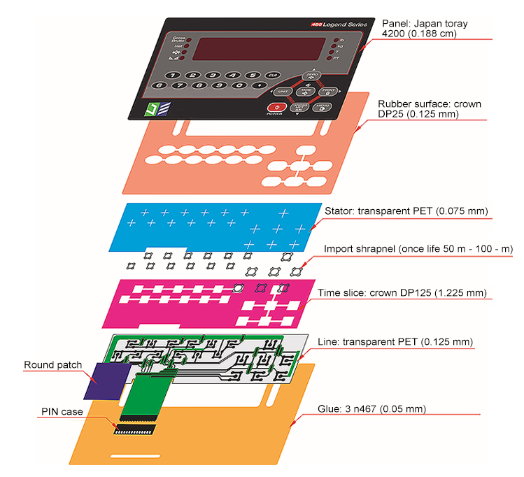
Exploded view showing complete five-layer membrane switch construction
Circuit Layers
Circuit layers provide electrical functionality through printed conductive traces on flexible substrates.
Substrate Materials:
- Polyester (PET): Most common, excellent dimensional stability, 0.125-0.188mm thickness
- Polycarbonate (PC): Higher temperature capability, used in demanding environments
- Polyimide (Kapton): Extreme temperature applications (-269°C to +400°C), flexible cables
Conductive Ink Selection:
- Silver ink: Standard choice, excellent conductivity (0.01-0.05 Ω/sq), cost-effective
- Silver/carbon blend: Better resistance stability over time and temperature, slightly higher cost
- Carbon ink: High resistance applications (>1kΩ/sq), lower cost, pressure-sensitive applications
- Copper circuits: Ultra-low resistance (<0.005 Ω/sq), used in high-current applications, requires protective coating
Circuit Design Rules:
- Trace width: Minimum 0.5mm for low-current (<100mA), 1.0mm+ for higher currents
- Trace spacing: Minimum 0.5mm between traces, 1.0mm preferred for reliability
- Contact pad size: Minimum 3mm diameter for tactile domes, 2mm for connector contacts
- Trace resistance: Calculate using sheet resistance × (trace length / trace width)
- Via connections: Avoid if possible; if required, use conductive rivets or epoxy with ±0.5mm positional tolerance
Spacer Layer
The spacer layer separates upper and lower circuits, preventing shorts and defining key actuation areas.
Spacer Material:
- Double-sided adhesive: 3M 9495MP (most common), polyester carrier with acrylic adhesive both sides
- Thickness: 0.125-0.175mm (5-7 mil) standard, thicker for greater tactile travel
- Actuation windows: Die-cut openings where upper and lower circuits make contact when pressed
Spacer Design Specifications:
- Window size: Typically 1-2mm smaller than tactile dome diameter to ensure reliable dome collapse
- Window-to-window spacing: Minimum 2mm web to prevent material tearing during manufacturing
- Edge distance: Minimum 3mm from spacer edge to nearest window for structural integrity
Backer Layer
The backer layer provides structural support and mounting surface for the membrane switch assembly.
Backer Options:
- Polyester film: Standard choice, provides stiffness without adding significant thickness (0.175-0.250mm)
- Rigid backer: FR4 PCB, aluminum, or stainless steel for applications requiring dimensional stability or EMI shielding
- Foam backer: 1-3mm foam provides cushioning and conforms to slightly uneven mounting surfaces
- No backer: Thin, flexible switches that mount directly to equipment surface
Backer Features:
- Stiffener areas: Thicker material sections around mounting holes prevent tearing
- Mounting holes: Punched or die-cut alignment holes for precise installation
- Grounding connection: Conductive areas for EMI shield grounding through mounting hardware
Graphic Design and Printing
Color Selection and Specifications
Color Systems:
- Pantone Matching System (PMS): Specify exact Pantone colors for consistent reproduction (e.g., PMS 286 Blue)
- CMYK process colors: Four-color printing for photographic images or gradients
- RGB conversion: Never provide RGB values—always convert to Pantone or CMYK for print production
Contrast Requirements:
- Minimum contrast ratio: 70% luminance difference between text and background for legibility
- High-visibility applications: Use maximum contrast (black on white or white on black)
- Color blindness considerations: Avoid red/green combinations; use blue/yellow or include shapes/symbols
Typography and Text
Font Selection:
- Sans-serif fonts: Arial, Helvetica, Futura for maximum legibility at small sizes
- Avoid serif fonts: Fine details lost at small sizes or with screen printing
- Minimum font size: 6pt (2mm height) for close viewing, 8-10pt (3-4mm) for arm's length, 14pt+ (5mm+) for distance viewing
- Font weight: Medium or bold weights—avoid light weights which may print inconsistently
Text Layout:
- All caps vs mixed case: Mixed case improves readability for longer text; all caps acceptable for single-word labels
- Line spacing: 1.2-1.5× font size for multi-line text
- Text-to-edge clearance: Minimum 2mm from button edge or graphic boundary
Icon and Symbol Design
Best Practices:
- Universal symbols: Use ISO 7000 or IEC 60417 standardized symbols when available
- Minimum feature size: 1mm for recognizable details
- Simplicity: Clear, simple icons work better than complex illustrations at small sizes
- Consistency: Maintain consistent line weights and style across all icons (2-3pt stroke weight typical)
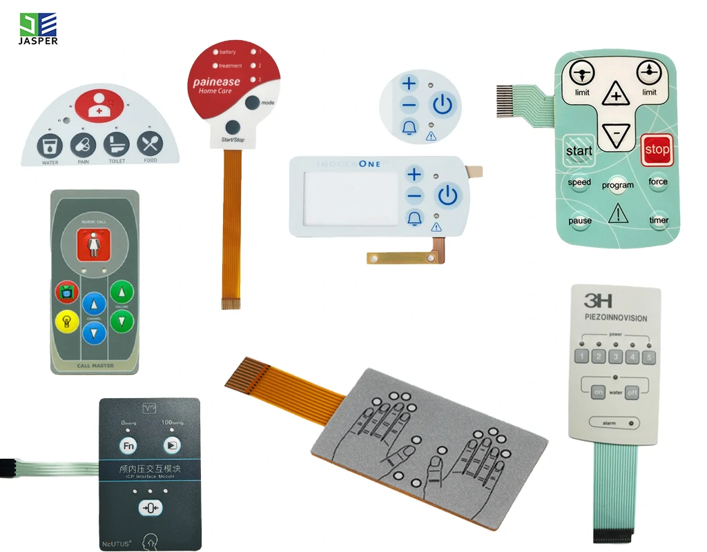
Professional graphic design examples demonstrating contrast, typography, and icon clarity
Dead Front Graphics
Dead front design hides inactive backlighting elements until illuminated:
- Light-blocking layer: Opaque black or dark gray printed behind translucent icons/text
- Translucent windows: Clear or colored translucent areas allow LED light through when activated
- Contrast enhancement: Dark background makes illuminated elements highly visible
- Professional appearance: Clean look when powered off, dramatic effect when backlit
Tactile Feedback Design
Metal Dome Selection
Metal domes create the tactile "snap" sensation confirming button activation.
Dome Specifications:
| Dome Diameter | Typical Force Range | Travel Distance | Applications |
|---|---|---|---|
| 6mm | 150-250gf | 0.3-0.4mm | Small buttons, consumer electronics, remotes |
| 8mm | 200-300gf | 0.4-0.5mm | Standard buttons, appliances, control panels |
| 10mm | 250-350gf | 0.4-0.6mm | Industrial controls, gloved operation (most common) |
| 12mm | 300-450gf | 0.5-0.7mm | Heavy-duty industrial, outdoor equipment |
Dome Force Selection Criteria:
- 150-200gf: Consumer products, gentle touch, precise control (calculators, remote controls)
- 200-280gf: General appliances, indoor controls, bare finger operation
- 280-350gf: Industrial standard, light glove operation, moderate vibration environments
- 350-450gf: Heavy gloves, high-vibration equipment, deliberate activation desired
- 450gf+: Safety-critical functions, prevention of accidental activation
Non-Tactile Designs
Non-tactile switches eliminate metal domes for flat, silent operation:
When to Use Non-Tactile:
- Silent operation required (audio recording studios, quiet environments)
- Ultra-thin profile needed (<1.5mm total thickness)
- Extended lifecycle requirement (10+ million actuations)
- Cost-sensitive applications
- Visual/software feedback sufficient for users
Non-Tactile Design Considerations:
- Circuit overlap area: Larger contact area (5-8mm diameter minimum) ensures reliable activation
- Actuation force: 80-150gf typical—just enough to flex overlay and close circuit
- Feedback alternatives: LED illumination, audible beep, vibration motor to confirm activation
Polydome Alternatives
Polymer domes provide softer, quieter tactile feedback:
- Material: Molded polyester or silicone
- Force range: 150-300gf, softer feel than metal domes
- Sound level: Significantly quieter than metal domes (10-20 dB lower)
- Lifecycle: 1-3 million actuations (lower than metal domes)
- Applications: Consumer electronics, handheld devices where quiet operation preferred
Circuit Design and Layout
Circuit Topology
Matrix vs Direct Wiring:
- Direct wiring: Each switch has dedicated circuit trace to connector—simple but requires n+1 connections for n switches
- Matrix scanning: Switches arranged in rows and columns—reduces connections (√n + √n for n switches) but requires scanning electronics
- Recommendation: Direct wiring for ≤8 switches, matrix for 9+ switches or when pin count must be minimized
Electrical Specifications
Contact Resistance:
- Target: <100Ω for reliable switching with standard microcontroller inputs
- Initial contact: Typically 10-50Ω when new
- End of life: May increase to 100-200Ω after 5 million cycles
- Design margin: Circuit should function reliably up to 500Ω contact resistance
Current Capacity:
- Silver printed traces: 1A maximum for 1mm wide trace, derate for higher temperatures
- Contact rating: Typically 100mA at 24V DC maximum for membrane switch contacts
- High current applications: Use copper flex circuits or external relay for switching >100mA
ESD Protection
Electrostatic discharge protection prevents circuit damage:
- ESD rating: Human Body Model (HBM) ±8kV direct contact, ±15kV air discharge (IEC 61000-4-2)
- Protection methods: TVS diodes, series resistors, capacitive filtering on circuit or in host device
- Grounded shields: Conductive layer between overlay and circuit, connected to ground

Professional circuit layout with optimized trace routing and contact pad placement
Connector and Tail Design
Tail Exit Options
Tail Exit Locations:
- Top exit: Connector leaves from top edge—cleanest appearance but cable visible
- Bottom exit: Connector leaves from bottom—most common, cable hidden behind/below panel
- Side exit: Left or right edge exit when top/bottom constrained
- Tail fold: Tail folds back for compact packaging or to route cable along mounting surface
Connector Types
ZIF (Zero Insertion Force) Connectors:
- Advantages: Easy assembly/disassembly, no soldering required, accommodates tolerance variations
- Typical pitch: 1.0mm or 1.25mm contact spacing
- Pin count: 4-40 contacts common
- Tail design: Stiffener section for connector insertion, contact pads with 0.5-1.0mm gold or tin plating
Crimp Connectors:
- Advantages: Secure connection, good vibration resistance, standard connector types available
- Common types: Molex, JST, TE Connectivity series
- Tail requirement: Exposed conductor area for crimp terminal attachment
Solder Pads:
- Advantages: Lowest cost, most secure connection, custom pitch possible
- Disadvantages: Requires soldering skill, not field-serviceable, heat exposure risk
- Pad specifications: 2mm × 3mm pads minimum, 0.5mm spacing, ENIG or HASL surface finish
Cable and Tail Specifications
Tail Length:
- Standard: 100-150mm (4-6 inches) from panel edge to connector
- Custom: Any length possible, but longer tails increase cost and routing complexity
- Strain relief: Reinforced section at panel-to-tail transition prevents cracking from repeated flexing
Tail Protection:
- Mylar cover: Protects traces from abrasion, standard for most applications
- Polyimide stiffener: Adds rigidity to connector area for easier insertion into ZIF connectors
- Overmolding: Rubber or plastic overmold at connector interface for maximum protection (IP67+ applications)
Embossing and Surface Features
Embossing Types
Pillow Embossing:
- Description: Raised dome over entire button area
- Height: 0.3-0.8mm typical
- Advantages: Clear button definition, tactile guidance, professional appearance
- Limitations: Requires 0.250mm minimum overlay thickness for depths >0.5mm
Rim Embossing:
- Description: Raised perimeter with flat center
- Height: 0.2-0.5mm
- Advantages: Defines button while maintaining flat surface for graphics or legends
- Applications: Buttons with detailed graphics or icons requiring flat print surface
No Embossing (Flat):
- Advantages: Easiest to clean, lowest cost, modern minimalist aesthetic
- Disadvantages: Less tactile guidance, button areas defined only by graphics
- Applications: Medical devices (sanitation priority), modern consumer products
Embossing Design Guidelines
- Minimum radius: 1.5-2.0mm corner radius to prevent stress concentration and cracking
- Draft angle: 3-5° sidewall angle for release from embossing tool
- Web width: Minimum 3mm between adjacent embossed features
- Edge clearance: Minimum 5mm from embossed feature to panel edge
- Emboss-to-print registration: Maintain ±0.5mm tolerance between embossed features and printed graphics
Backlighting Design
LED Placement Strategies
Edge Lighting:
- Method: LEDs mounted on circuit edge, light travels through light guide layer
- Advantages: Uniform illumination, lower LED count, cost-effective
- LED spacing: One LED per 30-50mm of panel edge
- Light guide: Clear polyester film (0.125-0.188mm) or dedicated light guide sheet
Direct Backlighting:
- Method: LED behind each button or graphic element
- Advantages: Individual control, bright localized illumination, multi-color possible
- LED placement: Center of button or graphic element, 1-3 LEDs per button depending on size
- Viewing angle: Use wide-angle LEDs (120°+) for uniform button illumination
LED Specifications
- LED type: SMD 0603 or 0805 package (edge lighting), 3mm or 5mm through-hole (direct)
- Color options: White (neutral, warm, or cool), red, green, blue, yellow, RGB for multi-color
- Brightness: 50-200 mcd for indoor, 500-2000 mcd for bright environments or outdoor
- Forward voltage: 2.0-2.2V (red), 3.0-3.4V (white, blue, green)
- Current: 10-20mA per LED typical
Graphic Design for Backlighting
- Translucent windows: Clear or lightly tinted areas for illuminated icons/text
- Light-blocking ink: Opaque layer around translucent windows prevents light bleed
- Window size: 20-30% larger than icon/text to allow light diffusion
- Brightness uniformity: Test prototypes to ensure even illumination without hot spots
Environmental Sealing Design
Achieving IP65 Rating
IP65 (dust-tight, water jet resistant) is the minimum standard for most industrial applications:
- Perimeter seal: Continuous 2-3mm adhesive border with no gaps or interruptions
- Surface preparation: Mounting surface must be flat (±0.5mm), clean, and dry
- Pressure application: 1-2kg per linear cm during bonding to ensure complete adhesive contact
- Cure time: 24-72 hours at room temperature for full adhesive bond strength
Achieving IP67/IP68 Rating
Submersible or extreme washdown applications require enhanced sealing:
- Wider seal border: 3-5mm adhesive border minimum
- Tail sealing: Epoxy potting, overmolding, or heat-shrink seal at cable exit
- Thicker overlay: 0.250-0.375mm polycarbonate resists water ingress better than thin polyester
- Gasket option: Silicone or EPDM rubber gasket between switch and mounting panel
- Pressure equalization: Gore-Tex vent for applications with significant temperature cycling
Connector Sealing
- Strain relief: Transition from rigid panel to flexible tail must be reinforced
- Tail exit sealing: Additional adhesive layer or potting compound at exit point
- Cable gland: Use IP-rated cable gland where tail exits enclosure
Dimensional Tolerances and DFM
Manufacturing Tolerances
Standard Tolerances:
- Overall dimensions: ±0.5mm for dimensions <100mm, ±1.0mm for 100-300mm
- Feature-to-feature: ±0.25mm for critical alignments (dome to circuit contact)
- Hole locations: ±0.25mm from nominal position
- Hole diameters: ±0.1mm for <5mm diameter, ±0.2mm for >5mm
- Layer-to-layer registration: ±0.3mm (standard), ±0.15mm (tight tolerance, higher cost)
Design for Manufacturing (DFM) Guidelines
Minimum Feature Sizes:
- Trace width: 0.5mm minimum (silver ink)
- Trace spacing: 0.5mm minimum
- Die-cut detail: 1.0mm minimum feature size
- Corner radius: 0.5mm minimum internal radius
Panel Size Constraints:
- Maximum panel size: Typically 300mm × 450mm (varies by manufacturer)
- Minimum panel size: 20mm × 20mm practical minimum
- Aspect ratio: Avoid extreme aspect ratios (>10:1) which complicate handling
Cost Optimization:
- Standard materials: Use manufacturer's standard material inventory to avoid minimum order charges
- Simplify graphics: Reduce color count (1-3 colors significantly cheaper than 4+ colors)
- Standard thicknesses: 0.175mm and 0.250mm most economical; custom thicknesses add cost
- Minimize custom features: Each custom requirement (special coatings, non-standard adhesives, unique connectors) adds cost
Prototyping and Testing
Prototype Development Stages
Stage 1: Concept Prototype
- Purpose: Evaluate layout, button placement, tactile feel
- Features: Printed graphics, tactile domes, basic circuit
- Omit: Final surface treatments, precise color matching, production adhesives
- Quantity: 3-5 units for internal evaluation
- Turnaround: 5-10 business days
Stage 2: Functional Prototype
- Purpose: Full functional testing, user trials, initial compliance testing
- Features: Production-intent materials, color-matched graphics, backlighting, final circuit design
- Quantity: 10-25 units for comprehensive testing
- Turnaround: 2-3 weeks
Stage 3: Pre-Production/Pilot
- Purpose: Manufacturing process validation, final design verification
- Features: Production tooling, production materials, full specifications
- Quantity: 50-100 units
- Turnaround: 3-4 weeks (includes tooling fabrication)
Testing Requirements
Functional Testing:
- Actuation force verification (±10% tolerance typical)
- Contact resistance measurement (<100Ω target)
- Electrical continuity testing (all circuits)
- Backlighting uniformity and brightness
Environmental Testing:
- Temperature cycling (-40°C to +85°C, 10+ cycles)
- Humidity exposure (85% RH, 85°C, 168 hours)
- IP rating validation per IEC 60529
- Chemical resistance (expose to application-specific chemicals)
Durability Testing:
- Life cycle testing (actuate to failure or specified cycle count)
- Abrasion testing (Taber abraser, 1000+ cycles)
- Adhesion testing (peel strength, 90° peel test)
Design Checklist
Use this comprehensive checklist before finalizing your membrane switch design:
Graphic Design
- ☐ All text minimum 2mm height (6pt font)
- ☐ Contrast ratio ≥70% between text and background
- ☐ Pantone colors specified (not RGB)
- ☐ Print-to-emboss registration tolerance defined
- ☐ Dead front features properly masked if backlit
Material Specifications
- ☐ Overlay material selected based on environment (PET vs PC)
- ☐ Overlay thickness appropriate for embossing depth
- ☐ Surface treatment specified (hard coat, anti-glare, antimicrobial)
- ☐ Adhesive selection matches temperature and chemical requirements
- ☐ Circuit substrate and ink type specified
Tactile Design
- ☐ Dome size and force rating selected for application
- ☐ Button size minimum 15mm for gloved operation
- ☐ Button spacing minimum 5mm edge-to-edge
- ☐ Tactile dome windows in spacer properly sized
Circuit Design
- ☐ Trace width ≥0.5mm minimum
- ☐ Trace spacing ≥0.5mm minimum
- ☐ Contact resistance calculated and acceptable
- ☐ ESD protection strategy defined
- ☐ Connector type selected and tail length specified
Environmental Sealing
- ☐ IP rating requirement defined
- ☐ Perimeter seal width adequate (2-5mm)
- ☐ Tail sealing method specified
- ☐ Mounting surface flatness verified
Manufacturing
- ☐ All dimensions within manufacturing tolerances
- ☐ No features smaller than minimum (0.5mm traces, 1mm details)
- ☐ Corner radii ≥0.5mm specified
- ☐ Panel size within manufacturer capabilities
- ☐ Assembly instructions provided
Documentation
- ☐ Dimensional drawing with tolerances
- ☐ Layer-by-layer specifications
- ☐ Bill of materials (BOM)
- ☐ Graphic artwork files (vector format)
- ☐ Testing requirements specified
- ☐ Compliance certifications required identified
Frequently Asked Questions
What software is used to design membrane switches?
Professional membrane switch design uses CAD software for technical drawings (AutoCAD, SolidWorks, DraftSight) and vector graphics software for artwork (Adobe Illustrator, CorelDRAW). Provide dimensional drawings in DWG or PDF format, and graphic artwork in AI, EPS, or PDF vector format. Avoid raster formats (JPG, PNG) for graphics as they don't scale properly. Most manufacturers accept these standard file formats and can work with your design files to create production tooling and specifications.
How thick should the graphic overlay be?
Standard graphic overlay thicknesses are 0.175mm (7 mil) for most applications, 0.250mm (10 mil) for heavy-duty use or deep embossing (>0.5mm depth), and 0.375mm (15 mil) for extreme durability or vandal-resistant applications. Thinner overlays (0.125mm / 5 mil) work for non-tactile switches or ultra-thin profiles. Polycarbonate is recommended for outdoor or medical applications, while polyester suffices for indoor consumer products. Thickness affects tactile response, durability, and embossing capability.
What actuation force should I specify for tactile domes?
Actuation force selection depends on user interface requirements: 150-200gf for consumer electronics with bare finger operation, 200-280gf for general appliances and indoor controls, 280-350gf for industrial applications with light glove use, and 400-450gf for heavy gloves or high-vibration environments. Most industrial applications specify 300-350gf as the optimal balance. Higher forces (450gf+) prevent accidental activation but may fatigue users in high-frequency applications. Always test prototypes with target users in actual operating conditions.
How long does it take to design a membrane switch?
Complete membrane switch design takes 8-12 weeks from initial requirements to production-ready specification: 1-2 weeks for requirements definition and concept design, 2-3 weeks for detailed engineering and documentation, 1 week for design review and manufacturability assessment, 2-3 weeks for prototype fabrication, 2-3 weeks for testing and refinement, and 1-2 weeks for final documentation and production release. Simple designs may be completed faster (4-6 weeks), while complex medical or aerospace applications may require 16+ weeks due to regulatory requirements and extensive testing.
Can I modify an existing membrane switch design?
Yes, existing designs can often be modified, but scope determines feasibility and cost. Simple changes (graphic updates, color changes, legend text) require only new printing screens ($200-500, 1-2 week turnaround). Moderate changes (button layout, add/remove buttons, resize panel) require new die-cutting tools ($500-1500, 2-3 weeks). Major changes (different materials, tactile to non-tactile, circuit redesign) may require complete re-engineering approaching new design cost. Always consult your manufacturer—they can advise whether modifications are practical or if new design is more cost-effective.
What are the most common membrane switch design mistakes?
Common design mistakes include: 1) Insufficient button size or spacing for gloved operation (use 15mm minimum), 2) Poor color contrast reducing legibility (<70% difference), 3) Inadequate perimeter sealing for IP rating requirement (<2mm border), 4) Wrong overlay material for application (polyester where polycarbonate needed), 5) Unrealistic tolerances (tighter than ±0.25mm adds significant cost), 6) Forgetting ESD protection in sensitive applications, 7) Insufficient tail strain relief causing connector failures, and 8) Not testing prototypes with actual users in real operating conditions before production.
References
- ISO 9355 - Ergonomic Requirements for the Design of Displays and Control Actuators
- ANSI/HFES 100 - Human Factors Engineering of Computer Workstations
- IEC 60529 - Degrees of Protection Provided by Enclosures (IP Code)
- IEC 61000-4-2 - Electromagnetic Compatibility - ESD Immunity Testing
- ISO 7000 - Graphical Symbols for Use on Equipment
- ASTM F1545 - Standard Test Method for Measurement of Switch Actuation Force