
Force sensing fundamentals for OEM teams
What Is a Force Sensing Resistor and How Does It Work?
A force sensing resistor, usually shortened to FSR, is a thin, passive, two-terminal resistive sensor whose electrical resistance normally decreases as applied force increases. It supports compact touch, presence, relative-force, and threshold decisions, but the final reading still depends on the mechanical stack, circuit, time under load, and calibration.
FSR decision stack
FSR at a Glance
| Question | Short answer |
|---|---|
| What changes under load? | The resistance between the two terminals normally decreases as force increases. |
| Does an FSR generate a voltage? | No. It is a passive resistive element and needs an external measurement circuit. |
| Is the response linear? | Usually not across the full usable range. The assembled system should be characterized and calibrated. |
| Does it measure force or pressure? | The sensing element responds to the load transferred into its active area. Contact area and load distribution affect the result, so pressure and force must not be treated as interchangeable. |
| Is it suitable for precise weighing? | Not by default. A strain-gauge load cell is usually a better starting point when traceable accuracy and long-term absolute measurement are primary requirements. |
| Where does an FSR fit well? | Thin force detection, relative force change, occupancy or presence detection, user input, threshold decisions, and custom sensing zones. |
How Does a Force Sensing Resistor Work?
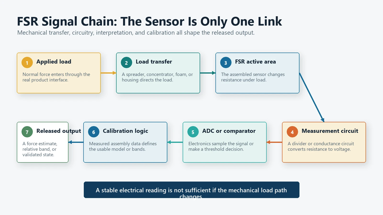
An FSR contains a force-sensitive resistive region connected to two conductors. In common polymer thick-film constructions, mechanical loading changes the conductive paths within the active material and the interface between layers. The measurable result is a lower resistance as more normal force is transferred into the active area.[1][4]
The exact layer construction, ink formulation, spacer design, electrode pattern, and protective films vary by sensor design. Those details matter, but an engineer integrating an FSR can start with a simpler system model:
Applied normal force
        |
        v
Load spreader or concentrator
        |
        v
FSR active sensing area
        |
        v
Resistance change
        |
        v
Voltage-divider or conductance circuit
        |
        v
ADC, comparator, or controller input
        |
        v
Calibrated force estimate or threshold decision
This signal chain explains why the sensing film alone does not determine performance. A stable electrical reading can still be misleading if the force reaches the active area through changing foam, a curved housing, a small moving contact, or a surface that introduces shear.
What happens when force is removed?
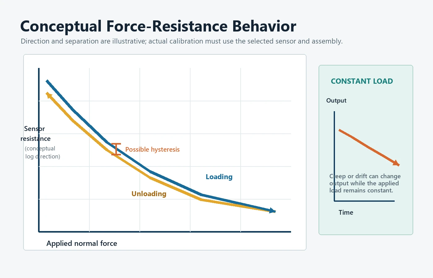
When the load is removed, resistance rises toward the unloaded state. The return path may not exactly retrace the loading path. This difference is called hysteresis. A reading can also change while a constant load remains applied, a time-dependent behavior commonly described as creep or drift.[4][5]
For threshold detection, these effects can often be handled through mechanical control, signal filtering, separate on/off thresholds, and validation. For absolute force measurement, they must be included in the error budget.
What Does the Electrical Signal Mean?
An FSR does not supply a calibrated force value by itself. The simplest interface is often a voltage divider. In the example below, the FSR connects to the supply and a fixed reference resistor connects from the output node to ground:
Vcc ---- FSR ----+---- Vout
                 |
              Rref
                 |
                GND
For that specific arrangement:
Vout = Vcc x Rref / (RFSR + Rref)
As force increases, RFSR normally decreases, so Vout rises. Reversing the resistor positions reverses the output direction. A designer can also use an operational-amplifier circuit to measure conductance rather than relying on a simple divider.
The reference resistor, supply voltage, ADC range, sampling rate, filtering, and allowed sensor current should be selected as one measurement system. A circuit that works on a bench can lose useful resolution when the real product applies force over a different range. Electrical limits should always follow the selected sensor’s data sheet.
Why a single conversion formula is rarely enough
The relationship between force and resistance is generally nonlinear. It can also vary with the mechanical interface and loading history. A logarithmic, piecewise, polynomial, or lookup-table model may fit one application, but the model should come from measured data in the intended assembly rather than from a generic curve copied from another sensor.
If the requirement is only “detect occupied” or “detect a press,” a calibrated threshold band may be more robust than converting every sample into a displayed force value.
Force and Pressure Are Not the Same Input
Force is measured in newtons. Pressure is force divided by area and is measured in pascals. If pressure is uniform, the relationship is:
Force = Pressure x Area
Real products rarely apply perfectly uniform pressure. A small boss, curved seat foam, finger, spring, or molded feature can concentrate the load. Two assemblies can apply the same total force but produce different FSR readings because the contact shape and load path differ.
This distinction is especially important in seat sensing. Foam thickness, trim tension, cushion contour, occupant posture, preload, and sensor position can alter the force delivered to the active area. The sensor should therefore be evaluated in the real seat stack, not only between two flat laboratory plates.
What Are the Main Strengths and Limitations of an FSR?
Strengths
- Thin and flexible form factor: An FSR can fit where a conventional load-cell structure would be difficult to package.[2]
- Simple resistance-based interface: Basic threshold systems can use a divider and comparator or an ADC input.
- Custom active areas and shapes: A printed sensor can be designed around a product’s available space, tail route, and detection zone.
- Useful relative response: The output can distinguish unloaded, lightly loaded, and more heavily loaded states after characterization.
- Suitable for threshold decisions: Presence, touch, squeeze, and occupancy logic often need a dependable state change more than laboratory-grade force accuracy.
Limitations
- Nonlinearity: Resistance does not normally change in a straight-line relationship with force across the whole range.
- Hysteresis: Loading and unloading can produce different outputs at the same nominal force.
- Creep and drift: Output may change while a constant load remains applied, and recovery can depend on time and load history.[5]
- Mechanical sensitivity: Load position, contact area, support stiffness, shear, and the interface material can change the reading.
- Unit-to-unit variation: A generic curve should not be treated as a guaranteed calibration for every part or assembly.
- Limited absolute accuracy without system control: An FSR can support useful force-related measurements, but it should not be specified as a precision scale merely because its output varies with force.
These are not reasons to avoid FSR technology. They are reasons to define the decision the sensor must make and validate that decision in the final construction.
How Should an FSR Be Mechanically Integrated?
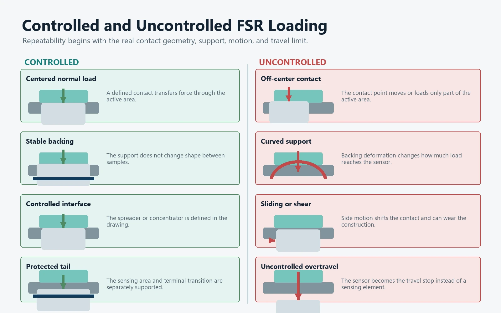
Mechanical integration often has more influence on repeatability than the choice of a more complicated conversion equation.
1. Support the sensor on a stable surface
The backing surface should be flat and stiff enough for the intended load. If the support bends differently from test to test, part of the force is spent deforming the structure instead of loading the active area consistently.
2. Apply force normal to the sensing area
FSRs are generally intended to receive compressive load through the active area. Sliding contact and side loading can create shear, wear the films, or move the contact point. Guide moving parts so the load approaches the sensor predictably.
3. Control the contact area
A load concentrator can help transfer force into a defined region, particularly when the contacting surface is larger than the sensor’s active area. It should be centered, repeatable, and compatible with the sensor supplier’s integration guidance.[3]
A concentrator that is too small can create a local stress peak. One that is too large can bridge onto the inactive border or surrounding structure. The correct geometry comes from the actual sensor, load range, and housing.
4. Prevent overtravel and overload
Where a mechanism can continue moving after the required force is detected, add a mechanical stop or another overload-control feature. The sensor should not be the only structure limiting travel.
5. Keep the stack-up repeatable
Adhesive, foam, elastomer, protective film, air gaps, and housing tolerances all affect load transfer. Specify these items in the drawing and sample build. Replacing a foam grade or adhesive thickness after calibration can change the result even when the FSR itself is unchanged.
6. Protect the tail and terminals
The sensing area and tail do different jobs. Avoid sharp folds, uncontrolled strain, rubbing edges, and connector loads that pull on the printed transition. Define bend radius, strain relief, connector orientation, and assembly handling.
Mechanical integration checklist
- [ ] Active area is aligned with the intended load path.
- [ ] Backing surface is stable across the full operating load.
- [ ] Contact geometry and material are defined on the assembly drawing.
- [ ] Normal load is separated from sliding or side load.
- [ ] Preload is measured and included in calibration.
- [ ] Overtravel or overload is mechanically controlled.
- [ ] Foam, adhesive, cover, and enclosure tolerances are included.
- [ ] Tail bend, strain relief, and connector routing are controlled.
- [ ] The test fixture reproduces the production load path.
- [ ] Calibration is performed after the sensor is installed in the representative stack.
How Should an FSR Be Calibrated and Validated?
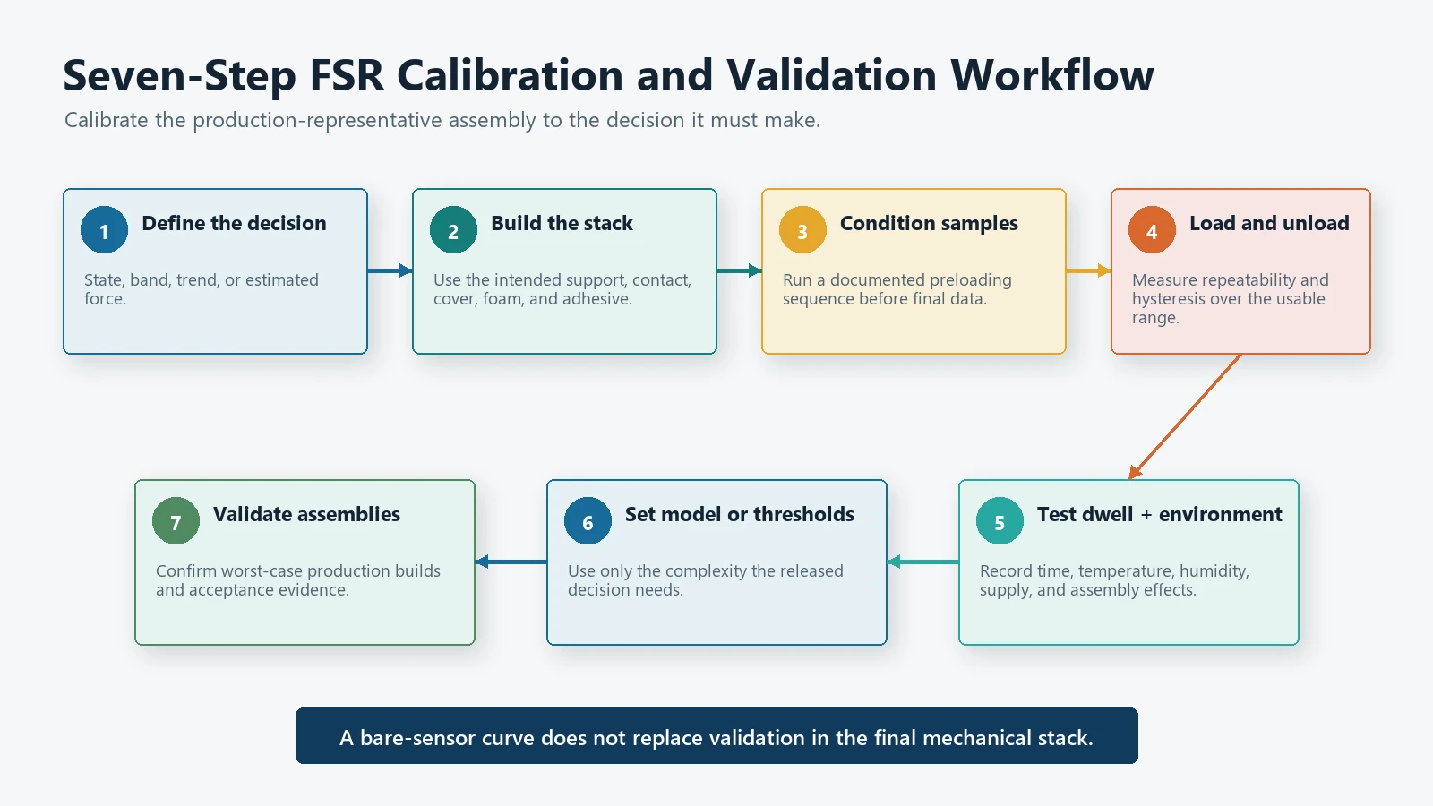
Calibration should answer a defined product question. “Make the sensor accurate” is not a testable requirement. “Detect a seated occupant above the agreed load condition without switching back during normal movement” is much closer.
Step 1: Define the measurand and decision
Choose whether the output will represent:
- a binary state;
- a relative force band;
- a trend or change;
- a multi-zone pressure pattern; or
- an estimated force value.
Do not collect high-resolution data if the product only needs one reliable state transition.
Step 2: Build the representative mechanical stack
Use the intended support, contact feature, adhesive, cover, foam, and enclosure. Record preload and assembly tolerances. A bare-sensor calibration is useful for incoming comparison but does not replace system calibration.
Step 3: Condition the sample
Apply a documented series of loads before collecting the final dataset. Conditioning reduces the chance that the first few loading cycles are mistaken for steady production behavior. Use a procedure appropriate to the chosen sensor and application.
Step 4: Measure loading and unloading
Collect several points over the actual operating range in both directions. Repeat the sequence to quantify repeatability and hysteresis. Include dwell periods if the product can remain loaded.
Step 5: Test time-dependent behavior
Hold representative loads for the longest meaningful operating interval and record output change. Then remove the load and record recovery. This step is essential when a seat, clamp, or fixture may remain loaded for minutes or hours.
Step 6: Include environmental and assembly variation
Evaluate the conditions that can change either the sensor or its load path. Depending on the application, that may include temperature, humidity, foam condition, mounting tolerance, supply variation, connector resistance, and part-to-part samples.
JASPER’s quality testing page describes the broader validation role, but the final test matrix must be matched to the customer’s drawing, risk analysis, and acceptance criteria.
Step 7: Choose the model or threshold logic
Fit only the complexity the application needs. For an occupancy decision, separate activation and release thresholds can prevent chatter around one boundary. For a force estimate, document the fitted model, valid range, residual error, sampling method, and out-of-range behavior.
Step 8: Validate in the final product
Repeat the decision test in production-representative assemblies, including worst-case tolerances. For automotive seating applications, the sensor output is only one input to the complete system. The vehicle or seat-system integrator remains responsible for final control logic, system safety analysis, compliance, and vehicle-level validation.
FSR vs Contact-Type Membrane Sensor vs Strain-Gauge Load Cell
| Selection criterion | Force sensing resistor | Contact-type membrane sensor | Strain-gauge load cell |
|---|---|---|---|
| Basic output | Variable resistance related to applied load | Open/closed or discrete switching state | Small bridge voltage related to structural strain |
| Best starting use | Thin relative-force or threshold sensing | A clear occupied/unoccupied or pressed/not-pressed decision | More accurate and stable force or weight measurement |
| Mechanical package | Very thin sensor, but load-transfer features still matter | Thin laminated switch with controlled actuation area | Requires a designed load-bearing structure |
| Electronics | Divider, conductance circuit, ADC, or comparator | Digital input or continuity circuit | Instrumentation amplifier and calibrated measurement chain |
| Linearity | Commonly nonlinear | Not intended as an analog force curve | Generally better suited to linear calibrated measurement |
| Hysteresis and creep | Must be characterized | Switch hysteresis depends on the mechanical structure | Present but usually more controllable in a properly designed load cell |
| Calibration need | System calibration is strongly recommended | Threshold validation is required | Calibration is required for force or weight accuracy |
| Good fit for seat occupancy | Yes, when force-related response adds value | Often the simpler choice for binary occupancy | Useful when the seat system is designed around measured structural load |
| Poor fit | Traceable high-accuracy weighing without a controlled system | Applications needing continuous force information | Ultra-thin flexible zones with no rigid load path |
No technology wins every row. If the project only needs a stable open/closed state, a custom pressure sensor mat may remove unnecessary analog calibration. If the project needs several flexible detection zones, a custom multi-zone pressure sensing layout may be more appropriate than one round FSR.
Where Are FSRs Used in OEM Products?
An FSR is a candidate when the product needs a thin sensing element and the mechanical design can deliver a controlled load. Typical engineering objectives include:
- detecting whether an object or occupant is present;
- recognizing a press, squeeze, grip, or clamp condition;
- comparing relative force between zones;
- confirming that a part reached a loaded position;
- adding a force threshold to a compact user interface; and
- monitoring changes where the output will be calibrated to the final assembly.
For seat projects, start with the seat occupancy sensor product hub rather than assuming every design should use an FSR. The correct architecture depends on the required output, number of zones, cushion stack, harness, connector, and system validation plan.
FSRs are a poor starting point when the buyer requires a legal-for-trade scale, a traceable laboratory force standard, or a long-term absolute reading without recalibration. They are also unnecessary when a simple contact closure fully satisfies the product requirement.
What Information Is Needed for a Custom FSR Review?
An effective RFQ describes the complete sensing problem, not only the sensor diameter.
Send the following where available:
- Application and decision: What must the system detect or estimate?
- Drawing or available envelope: Overall sensor outline, active area, keep-outs, holes, tail direction, and mounting space.
- Load information: Expected minimum, normal, and maximum force; preload; contact area; load duration; and loading rate.
- Mechanical stack: Support material, actuator or load spreader, foam, cover, adhesive, enclosure, and permitted travel.
- Electrical target: Divider or amplifier concept, supply and ADC range, target threshold or output bands, and connector pinout.
- Environment: Temperature, humidity, cleaning chemicals, fluids, vibration, and expected storage conditions.
- Lifecycle and validation: Number of cycles, dwell time, repeatability target, acceptance criteria, and required test reports.
- Manufacturing inputs: Prototype quantity, annual volume, cable or tail requirement, connector, assembly needs, and schedule.
If the load path is still uncertain, a prototype review should resolve the mechanical interface before production tooling or firmware thresholds are frozen.
Frequently Asked Questions
Is an FSR the same as a pressure sensor?
Not exactly. An FSR responds to the load transferred into its active area. Pressure describes force per unit area. Because contact area and load distribution affect the reading, an FSR should not be treated as a calibrated pressure sensor unless the mechanical interface and calibration specifically support that measurement.
Can an FSR measure weight?
It can produce an output related to an applied weight in a controlled setup, but that does not make it a precision scale. If absolute accuracy, long-term stability, and traceable calibration are primary requirements, compare the FSR approach with a strain-gauge load cell.
Why does the reading change while the force stays constant?
Time-dependent output change can come from the FSR material, viscoelastic interface materials, seat foam, adhesive, enclosure deformation, temperature, or the measurement circuit. Test the complete assembly under the intended dwell time before assigning thresholds.
Does a larger FSR measure more force?
Not automatically. Active-area size, electrode design, contact shape, load distribution, and sensor construction all matter. Select the geometry from the product requirement and validate it with the real loading interface.
Can one calibration curve be used for every assembly?
Only if testing demonstrates that the variation is acceptable. A production plan should account for sensor variation, assembly tolerance, preload, interface materials, electronics, and environment. Some products use a family calibration or threshold window; others require individual calibration.
When should an OEM choose a contact-type membrane sensor instead?
Choose the contact-type route when the system only needs a dependable open/closed state and continuous force information adds no value. It can simplify the circuit, calibration, and acceptance test.
Review a Custom FSR Sensor Requirement
Share the drawing, active sensing area, load path, expected force range, output decision, connector, environment, prototype quantity, and validation target through the JASPER request-for-quote form. The engineering review should first confirm whether an FSR, contact-type membrane sensor, multi-zone pressure mat, or another sensing structure is the right fit.
Sources
- Interlink Electronics, “FSR 400 Series,” product data and integration notes.
- Tekscan, “Embedded Force Sensors,” FlexiForce product and integration overview.
- Tekscan, FlexiForce integration guidance, including mechanical loading, force concentrators, support surfaces, and calibration in the intended assembly. Resource family available from the Embedded Force Sensors page.
- L. Paredes-Madrid, C. Palacio, A. Matute, and C. Parra Vargas, “Underlying Physics of Conductive Polymer Composites and Force Sensing Resistors (FSRs) under Static Loading Conditions,” Sensors, 2017.
- L. Paredes-Madrid, A. Matute, J. Bareno, C. Parra Vargas, and E. Gutierrez Velasquez, “Underlying Physics of Conductive Polymer Composites and Force Sensing Resistors (FSRs). A Study on Creep Response and Dynamic Loading,” Materials, 2017.