
THE ESSENTIAL GUIDE
What Is a Membrane Switch?
Understand the construction. Compare the options.
Specify the right interface for your equipment.
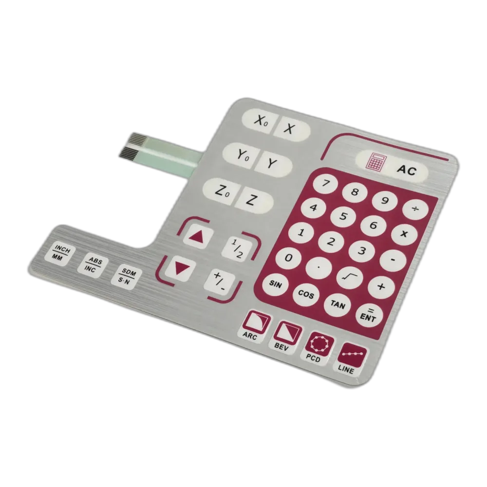
Membrane keypad · graphic face and flexible connection
Explore the 12 chapters
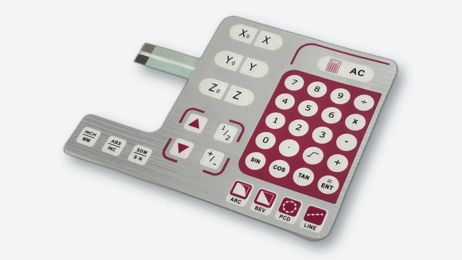
A membrane switch is a thin electrical switching assembly that lets users control equipment by pressing marked key areas. It combines printed graphics, electrical contacts, circuit layers, and adhesives into a low-profile interface. Pressing a key closes a circuit; releasing it normally opens the circuit again. The equipment controller detects this change and responds to the user’s command.
The visible surface identifies functions such as power, settings, or navigation, while the underlying circuit performs the switching. A membrane switch is therefore more than a printed label: it is a functional input device.
For engineers and buyers, understanding membrane switch construction helps turn a panel drawing into a workable specification. This guide explains how the technology operates, which materials and circuit options are available, and what to consider before requesting a custom design.
How Does a Membrane Switch Work?
Most conventional membrane switches use momentary, normally open contacts. In a printed-contact design, a spacer separates conductive surfaces. Pressing the flexible key area brings those surfaces together, creating an electrical connection. When pressure is removed, they separate. The switch usually provides a low-voltage, low-current control signal rather than directly switching a machine’s power load.
Tactile Membrane Switches
A tactile membrane switch provides a noticeable snap when pressed. This response commonly comes from a stainless-steel metal dome or a formed polyester dome. In a metal-dome arrangement, the dome deflects to bridge circuit contacts and returns to its original shape after release. The tactile response gives the operator physical feedback.
Non-Tactile Membrane Switches
A non-tactile membrane switch closes its contacts without a pronounced snap. The equipment may confirm input through a light, sound, or display response. Both tactile and non-tactile versions can serve as control inputs; the difference concerns the operating feel, not whether the key performs an electrical function.
Electrical Signals and the Equipment Controller
The contacts provide an input signal. They are not a communications interface. The controller supplies the sensing circuit, interprets a closure, and decides what the equipment should do. A printed keypad does not inherently output USB, CAN, or another digital protocol; that requires additional electronics.
Specify the permitted sensing voltage and current, maximum closed-circuit resistance, and required open-circuit isolation. Those limits must suit the complete path through the tail, printed traces, contacts, and connector—not just the dome. LED power and control connections also need their own circuit definition.
Matrix Wiring and Ghosting
A matrix connects keys between rows and columns so the controller can identify their intersections. For example, a 4 × 4 matrix provides 16 key positions using eight row/column lines, excluding lighting and other connections. The benefit is a smaller connection count; the trade-off is scanning logic and multi-key handling.
Several simultaneous key presses can create ambiguous electrical paths in some scanning arrangements. The controller may then report a key that was never pressed. This is ghosting. Define allowable simultaneous presses before choosing the matrix, scanning method, and any isolation diodes. Firmware that rejects ambiguous combinations is different from hardware that supports those combinations correctly.
Contact Bounce and Debouncing
A closing contact can briefly make and break before settling. Without debouncing, the electronics may count one press more than once. Debouncing is handled by the controller or interface circuit; it is not supplied by the printed graphics.
Measure the contact behavior, then set the detection timing to reject bounce while retaining the required response to short presses, held keys, and release. A fixed delay copied from another product is not an acceptance test.

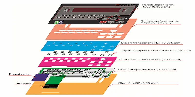
What Are the Layers of a Membrane Switch?
There is no single layer count that applies to every design. A printed-contact keypad, a metal-dome assembly, and a PCB-based interface can have different constructions. The following table describes common components rather than a mandatory stack for every product.
| Layer or component | Main function |
|---|---|
| Graphic overlay | Displays legends, symbols, colors, and branding; may include embossed keys and transparent windows. |
| Overlay adhesive | Bonds the graphic surface to the layers beneath it. |
| Dome retainer or upper contact layer | Holds tactile domes in position or carries the moving contacts, depending on the design. |
| Spacer | Maintains separation and provides room for the switching action. |
| Circuit layer | Carries conductive paths between the keys, indicators, and electrical connection. |
| Rear adhesive | Attaches the assembly to its mounting surface. |
| Optional support and functional layers | Provide rigid backing, illumination, or electrical shielding where required. |
The exact arrangement depends on the switching mechanism and additional functions specified for the assembly.
These layers must work together. The overlay, spacer, and supporting surface influence how the finished key feels; selecting a dome alone does not define the complete actuation force. Connections also need space within the enclosure, whether the design uses a flexible tail or board-mounted termination.
The drawing should also identify local thickness changes around domes, LEDs, windows, and stiffeners. A nominal overall thickness does not show whether the enclosure will press unintentionally on a key or obstruct its movement. Keep sealing lands, component spaces, and connector exits clear in the mechanical layout.
What Materials Are Used in Membrane Switches?
Membrane switch materials serve different jobs: the overlay faces the user and environment, the circuit carries signals, and the adhesive couples the layers to each other and the enclosure. Compare material grades in their intended layer, not polymer names in isolation.
Polyester and Polycarbonate Overlays
Polyester, commonly called PET, and polycarbonate, or PC, are widely used graphic overlay materials. Both support printed graphics, windows, and different surface finishes. Selection should consider repeated flexing at key areas, appearance, cleaning exposure, and the required finish rather than relying only on the polymer name.
Hardcoated film grades can provide abrasion resistance, chemical resistance, and different textures. However, these properties depend on the specific film and coating. A material intended for an indoor control panel should not automatically be specified for prolonged outdoor exposure.
| Material and role | Useful selection direction | What to verify |
|---|---|---|
| PET graphic overlay | Repeatedly flexed key areas; textured or clear protective surfaces | Film thickness, emboss geometry, hardcoat, cleaning compatibility, and specified UV exposure |
| PC graphic overlay | Clear windows and graphics where the selected grade and finish fit the panel | Actual flexing duty, chemical compatibility, scratch protection, and outdoor suitability |
| Heat-stabilized PET circuit film | Printed conductive patterns in a thin laminated keypad | Ink adhesion, print/cure compatibility, dimensional stability, and component-attachment process |
| Polyimide FPC substrate | Etched copper routing and soldered connections | Bend zones, coverlay, stiffeners, component support, and connector interface |
PET and PC are both available as hardcoated interface films; neither name alone guarantees a particular outdoor or cleaning rating. Heat-stabilized PET circuit films and polyimide FPC substrates should not be confused with the visible overlay material.
Surface Finishes and Windows
The operating area and display window may need different optical properties. A textured finish may be appropriate around the keys, while a viewing window may require greater clarity. For illuminated areas, specify whether the window should transmit light directly or diffuse it to reduce visible hot spots.
Review lighting samples under representative conditions. Window transparency, ink treatments, and LED placement affect the brightness and uniformity seen by the user.
Conductive Materials
Printed-film circuits commonly use silver conductors, sometimes with carbon at selected contact areas. Copper conductors are used in FPC and rigid PCB constructions. The required routing, component connections, and mechanical format help determine which circuit technology is appropriate.
Adhesives
Pressure-sensitive adhesives bond the internal layers and attach the switch to the equipment. Adhesive selection depends on the actual mating surface, its texture and surface energy, and environmental exposure. A bond that works on a smooth metal panel may not perform identically on a textured plastic housing.
What Are the Main Types of Membrane Switches?
Membrane switch types are best understood as independent design dimensions. Choose the circuit, feedback, lighting, protection, and integration separately, then check whether the combination can be manufactured and installed within the available space.
Membrane switches can be classified by circuit construction, tactile response, sealing, or illumination. These categories overlap: a single assembly may use an FPC circuit, tactile keys, perimeter sealing, and LED-based backlighting.
| Classification dimension | Main options | Selection question |
|---|---|---|
| Circuit construction | Printed silver/PET, copper FPC, rigid PCB | What routing, component attachment, and mechanical support are required? |
| Tactile response | Metal dome, formed polyester dome, non-tactile contacts | What should the operator feel, and how will input be confirmed? |
| Illumination | Direct LED, LED with LGF, EL, fiber-optic distribution | Which regions must illuminate, with what space and power available? |
| Environmental and electrical protection | Perimeter sealing, enclosure seals, EMI/RFI/ESD measures | What exposures and electrical disturbances must the installed assembly withstand? |
| Mechanical and electronic integration | Flat overlay, silicone hybrid, backplate, connectors, embedded components | Which parts belong in the keypad assembly and which remain in the equipment? |
These labels are not interchangeable. A waterproof FPC switch can also be tactile and LED-backlit. “Custom” describes the specification process, not another electrical switching mechanism.
Silver-Flex Membrane Switches
Silver-flex membrane switches use conductive silver ink printed onto flexible polyester. They are a common choice for relatively straightforward control panels where thin construction and economical production are priorities. Suitability still depends on circuit complexity, operating conditions, and the method used to attach any electronic components.
FPC Membrane Switches
FPC membrane switches use flexible printed circuits with copper conductors, commonly on polyimide film. They support finer routing and soldered component connections, making them worth considering when a compact interface requires more complex circuitry. Flexibility does not remove the need to review bend locations, connector support, and assembly constraints.
PCB Membrane Switches
PCB membrane switches use a rigid printed circuit board as part of the switching assembly. The board can provide structural support and accommodate mounted components and connectors. This format is useful when the interface benefits from a rigid circuit platform, but the available thickness and mounting arrangement must be checked.
Metal-Dome, Polydome, and Non-Tactile Constructions
A metal-dome design uses a separate spring-metal element for tactile feedback and electrical contact. It is a useful candidate when a distinct snap helps the operator confirm a command. Dome location, retention, contact geometry, and the supporting stack must stay controlled.
A polydome is a formed polyester dome, not simply a raised printed key label. In a conductive polydome design, a printed contact on the formed film closes the circuit. It can provide a softer tactile response and reduce separately placed dome components, but tooling, formed geometry, and changes in feel during use still require evaluation. Both metal domes and polydomes are tactile options.
Non-tactile printed-contact designs avoid the snap mechanism. They suit controls where a light, beep, or display gives sufficient confirmation. A quiet interface is possible, but the user still needs to know whether a command registered. Do not equate “non-tactile” with “capacitive.”
Waterproof and Sealed Membrane Switches
Waterproof membrane switches require attention to the complete sealing design. A continuous front overlay helps protect the face, but exposed edges, openings, and connections remain potential entry points. Perimeter seals, suitable adhesives, and enclosure design must be considered together.
An IP rating describes enclosure protection against specified ingress conditions. It should not be assumed from the presence of a membrane overlay. Define the intended exposure and verify the protection of the relevant assembly in its intended installation.
Shielded Membrane Switches
Shielded constructions add conductive shielding and a defined connection to the equipment's grounding or chassis strategy. They can address electromagnetic interference (EMI), radio-frequency interference (RFI), or electrostatic discharge (ESD), depending on the design. A shield with an unspecified termination is an incomplete requirement.
Discuss shield coverage, display openings, tail routing, and connection continuity alongside the controller electronics. Validate the installed interface with the equipment; a shielding layer alone does not establish EMC compliance.
Silicone-Rubber Hybrid Keypads
A molded silicone keytop or boot can be placed over a membrane circuit and tactile layer. This combines three-dimensional keys or a sealed front shape with the chosen electrical construction. It can help when grip, key separation, or an enclosing boot matters, but adds molded geometry, tooling, and force-transmission details to review.
Not every silicone keypad is a membrane switch. A separate rubber keypad may instead use conductive pills to contact a PCB. Ask whether the quotation includes only molded rubber, a circuit, or a complete laminated and mounted interface.
Backlit Membrane Switches
Backlit membrane switches illuminate key legends or other selected areas. This is different from simply adding a small status indicator beside a key. LEDs may illuminate local regions directly or work with a light-guide film to distribute light over a larger area. LGF is a light-distribution component, not an independent light source.
An EL backlit membrane switch uses an electroluminescent lamp layer instead. EL can provide thin, broadly distributed illumination and requires a compatible electrical driver. Compare the complete lighting system, including uniformity, thickness, power supply, and expected operating conditions, rather than selecting a technology by name alone.
| Lighting arrangement | Where it helps | Main trade-off or check |
|---|---|---|
| Direct LEDs | Individual indicators or small illuminated areas | Position, diffusion, hot spots, drive current, and component support |
| LEDs with light-guide film (LGF) | Distributing light across selected legends with limited front-panel depth | Light extraction, masking, optical isolation, and room for LED coupling |
| Electroluminescent (EL) lamp | A thin illuminated area with broad light distribution | Compatible driver, supply integration, brightness change over time, and electrical noise |
| Fiber-optic panel with a separate source | Specialized layouts or designs that benefit from remotely coupled illumination | Source coupling, fiber routing, panel stack, uniformity, and supplier availability |
The lighting system changes the stack, power requirements, and visible result—not the underlying contact principle.
Fiber-optic backlighting distributes light from a separate source through optical fibers. It is another light-distribution approach, not a self-powered luminous layer. For an existing fiber-optic design, compare a supported replacement against LED/LGF alternatives; for a new design, verify the complete optical arrangement and supply support before specifying it.
Integrated Assemblies and Adjacent Touch Technologies
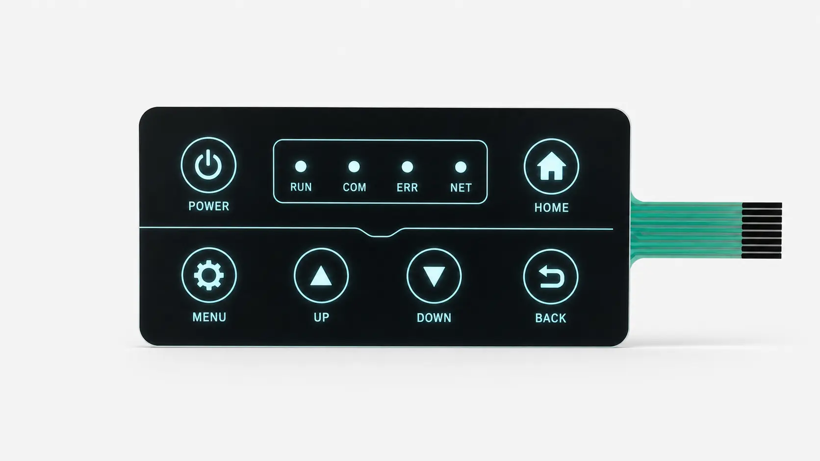
A membrane switch may be supplied with a rigid backplate, display window, connectors, resistors, LEDs, or additional electronics. Define these as assembly features. An integrated controller changes the electrical interface and test scope; it does not make a plain contact sheet a digital communications device.
Capacitive controls detect changes in capacitance and need a suitable sensing circuit. Cover thickness, moisture, and glove use must be considered during sensor design and tuning. A resistive touchscreen measures touch position through resistive layers brought into contact by pressure.
These are adjacent HMI technologies, not subclasses of the mechanically actuated membrane switches described here. They can share a front-panel assembly, but their sensing, feedback, electronics, and validation requirements differ.
What Are the Advantages and Limitations of Membrane Switches?
Main Advantages
Membrane switches combine graphics and electrical input in a compact assembly. Their low profile suits equipment with limited panel depth, while customizable shapes, colors, and legends help match the interface to its functions. A continuous front surface also makes routine wiping more straightforward than cleaning around numerous separate keycaps.
Depending on the design, the assembly can integrate tactile keys, windows, indicators, backlighting, and shielding. This allows several front-panel functions to be considered together instead of treating each feature as an unrelated component.
Design Limitations
Key travel is generally short, and the feel differs from that of many discrete pushbuttons. A fixed printed layout is less adaptable than a screen whose controls change through software. Added lighting, support, and components can also increase thickness and complexity.
Treat sealing, chemical resistance, and durability as design requirements to validate, not automatic properties of every membrane switch. Material compatibility and prototype testing remain important even when the basic construction appears simple.
Serviceability and Consequences of Failure
A bonded multilayer assembly can be difficult to repair at an individual contact or LED. Consider the replacement unit, access to the tail connector, and the availability of replacement artwork and parts. A low component price is less useful if enclosure disassembly dominates service cost.
Also separate an ordinary operator input from a safety-related function. A key labelled “STOP” does not by itself make the switch, controller, or machine a validated emergency-stop system.
Membrane Switch vs Mechanical Switch: What Is the Difference?
Here, “mechanical switch” refers to a discrete pushbutton or key switch; a conventional membrane switch also operates through mechanical movement. The useful comparison is therefore between complete interface arrangements, not between “moving” and “non-moving” technologies.
| Consideration | Membrane switch interface | Discrete pushbutton interface |
|---|---|---|
| Front surface | Often a continuous printed overlay | Separate actuators within a panel |
| Key travel | Usually short | Varies; longer-travel options are available |
| Graphics | Integrated into the overlay | May require separate legends or labels |
| Sealing | Depends on the overlay, edges, and installation | Depends on each switch and its panel mounting |
Neither approach is universally better. Compare the required tactile feel, panel space, cleanability, and installation.
A touchscreen may be another option when changing menus or complex information displays are central to the interface. It can also be combined with physical controls rather than treated as an all-or-nothing alternative.
If the job is to interrupt a power circuit directly, select an appropriately rated switching device and system architecture. A low-current membrane input may command that architecture, but its attractive front surface does not establish load-breaking capability.
Where Are Membrane Switches Used?
Membrane switches are useful where equipment needs a defined set of commands in a compact, labelled interface. The application determines the specification: cleaning, gloves, lighting, water, vibration, or public use may matter more than the industry name.
Medical and Laboratory Equipment
Membrane switch applications include diagnostic instruments, monitoring equipment, and laboratory controls. For a device cleaned frequently, the important specification is not simply “easy to clean”: identify the cleaning agents, exposure conditions, and required readability so the materials can be evaluated appropriately.
Medical Equipment
For a monitor or diagnostic device, distinguish an ordinary command from an action with a high consequence if selected accidentally. Review key spacing, readable labels, tactile confirmation, and the response shown by the equipment. Cleaning and usability checks belong on the finished panel, with the specified gloves and cleaning procedure.
Wipe disinfection is not the same exposure as steam sterilization. If a part must undergo an autoclave process, every film, adhesive, connector, and component needs a construction and validation plan for that process; a wipe-clean overlay is not enough.
Laboratory Equipment
For analyzers, balances, and benchtop instruments, identify the actual reagents, spill locations, and cleaning agents near the controls. A useful configuration may combine tactile keys, a clear display window, and a circuit chosen for the required indicators. Check readability, key operation, and bond integrity after representative chemical exposure—not only on an unused sample.
Industrial Controls and Instruments
Industrial equipment uses membrane interfaces for selecting modes, entering settings, and operating defined controls. Design reviews should consider contaminants, operating temperature, available mounting space, and the operator’s interaction with the panel. For a gloved-use application, evaluate the finished prototype with representative gloves rather than judging the artwork alone.
Commercial and Consumer Equipment
Appliances and commercial devices also use membrane keypads. A fixed set of controls can combine familiar symbols and branding within one front panel. The design still needs to match the actual use conditions; a protected indoor appliance and an outdoor access panel should not share specifications merely because their key layouts look similar.
Application Configuration and Validation Matrix
The following are engineering selection scenarios, not fixed recipes or claims that one manufacturer supplies every application. Each proposed configuration needs to be checked against the equipment's actual requirements.
| Equipment scenario | Main design concern | Configuration to evaluate | Validation priority |
|---|---|---|---|
| Medical monitors and diagnostic devices | Frequent cleaning and unambiguous commands | Tactile keys, readable windows, compatible overlay and seals | Specified cleaning cycles, gloves, user confirmation, and electrical behavior |
| Laboratory analyzers and balances | Reagent spills and display visibility | Chemical-compatible front film, protected window, appropriate PET/FPC/PCB circuit | Actual reagent contact, readability, key response, and adhesive condition |
| Industrial machine controls | Gloves, oils, dirt, and vibration | Distinct tactile keys, sealed perimeter, supported tail and components | Gloved operation, contaminant exposure, vibration, and installed key feel |
| Test and measurement instruments | Compact controls near displays and sensitive electronics | Fine-routing FPC or supported PCB, indicators, shielding where required | Electrical thresholds, signal interference, window clarity, and connector fit |
| Home appliances | Steam, grease, repeated wiping, and limited depth | Printed PET circuit or another suitable circuit beneath a cleanable overlay | Heat/humidity at the panel, cleaning compatibility, and repeated operation |
| Commercial POS terminals | Repeated commands and cleaning in a busy workspace | Clearly grouped keys, readable legends, suitable tactile feedback | Repeated-use pattern, abrasion, cleaning, and connection reliability |
| Kiosks and vending machines | Public handling, spills, and changing ambient light | Protected membrane keypad, sealed edges, lighting where useful | Spill paths, impact/abrasion exposure, legibility, and maintenance access |
| Fitness equipment and treadmills | Sweat, cleaning, and operation while moving | Larger differentiated controls, tactile response, secure mounting | Wet/gloved fingers as applicable, mis-presses, vibration, and repeated-use duty |
| Beauty and aesthetic equipment | Treatment products, frequent cleaning, and easy mode recognition | Compatible overlay, grouped controls, clear status lighting | Named creams/disinfectants, residue, label contrast, and command confirmation |
| Marine and outdoor controls | Sunlight, salt, rain, and water at panel edges | Outdoor-qualified materials, complete sealing, supported connections | UV/weather exposure, salt conditions, ingress, and daylight/night readability |
| Pool and spa equipment | Persistent moisture, treatment chemicals, and warm surroundings | Sealed front assembly or silicone hybrid with protected terminations | Specified water chemistry, condensation, thermal exposure, and mounted sealing |
| Security and access controls | Repeated numeric entry, wear, and weather at entrances | Wear-resistant legends, tactile keypad, defined multi-key behavior | Worn-key readability, permitted combinations, ESD, and exposure at installation |
| Vehicle auxiliary equipment | Vibration, temperature change, and gloved use | Supported circuit and connector, tactile controls, appropriate front sealing | Vehicle mounting loads, temperature cycling, user access, and electrical disturbances |
| Agricultural machinery | Dust, mud, chemicals, sunlight, and washdown | Readable large controls, compatible materials, sealed mounting and connections | Actual chemicals, washing procedure, vibration, and operation with work gloves |
The medical, industrial, appliance, fitness, marine, and spa examples build on documented membrane-keypad applications. The configuration and test columns apply those design principles to the stated conditions; they are not performance ratings.
Match the Interface to the Task
Use a membrane keypad when the operator benefits from fixed, identifiable controls. If a public kiosk requires strong impact resistance, evaluate a protected panel or a different actuator construction. If a screen changes functions frequently, fixed printed legends may need a complementary display.
For treadmills, machinery, vehicle equipment, and other systems where unintended operation matters, assess the complete controls and protective functions. Selecting a tactile membrane switch is only one part of that engineering work.
How Are Membrane Switches Manufactured?
Manufacturing begins with an engineering review of dimensions, artwork, circuit requirements, and the proposed layer construction. For printed-film versions, graphics and conductive patterns are printed onto their respective materials and cured as required.
The layers are cut to shape, components are positioned, and the assembly is aligned and laminated. Registration matters because the printed key areas must line up with the switching contacts, domes, and windows. FPC and PCB designs use their corresponding circuit fabrication and component-assembly processes rather than relying entirely on printed silver circuitry.
Production checks typically address appearance, dimensions, circuit continuity, and specified key or LED functions. Qualification testing may additionally cover repeated operation and environmental exposure. Agree which checks apply to every unit and which are performed on samples during validation.
Manufacturing and Acceptance Checkpoints
| Stage | What to control | Useful acceptance record |
|---|---|---|
| Engineering release | Artwork, pinout, layer stack, tolerances, and component list | Approved revision with critical dimensions and test requirements |
| Incoming materials | Film/adhesive grade, circuit and component identity | Traceable material and component records against the released specification |
| Printing and circuit preparation | Registration, conductor continuity, dielectric separation, and curing | Inspection or electrical results appropriate to the process |
| Cutting and forming | Key, window, tail, and sealing geometry | Dimensional and visual checks against the drawing |
| Placement and lamination | Dome/LED alignment, cleanliness, and consistent stack assembly | Controlled assembly instructions and defined inspection points |
| Final test and packing | Key mapping, open/short conditions, LEDs, appearance, and handling protection | Agreed test coverage, defect criteria, and lot identification |
A visually acceptable sample can still have an incorrect pinout or intermittent connection. Conversely, an electrical continuity test does not prove sealing or long-term key feel. Keep the acceptance records specific to what was actually tested.
Common Failures and Installation Controls
| Symptom | Possible mechanism to investigate | Prevention or verification focus |
|---|---|---|
| Lifting edges or bubbles | Contamination, inadequate surface contact, or an unsuitable adhesive/substrate pair | Surface preparation, correct adhesive grade, application process, and bond evaluation |
| Intermittent keys or an open circuit | Damaged tail, connector mismatch, or stressed conductors | Tail protection, bend control, connector engagement, and electrical testing while installed |
| Uneven or lost tactile response | Misalignment, wrong stack geometry, or unsupported actuation | Registration, dome/overlay relationship, mounting support, and force measurement |
| Failed or intermittent LEDs | Component connection damaged by handling, flexing, or environmental stress | Supported component zones and a suitable attachment method |
| Unwanted inputs after liquid exposure | Leakage, contamination, or water entering an unprotected path | Seal continuity, protected terminations, isolation checks, and exposure testing |
| Faded or damaged legends | Abrasion, incompatible cleaning, or unsuitable outdoor film | Qualified finish and a representative wear/chemical/weathering test |
These are diagnostic possibilities, not a remote diagnosis from appearance alone. Trace the fault electrically and inspect the installed construction before replacing a material or component.
Install the switch on the specified clean, dry mounting surface using the adhesive supplier's application conditions, pressure, and bond-development time. Keep the liner in place until needed. Route the tail without a sharp crease, protect it from enclosure edges, and support the connector. Do not force a tail into a mismatched connector or repeatedly peel and reapply a bonded assembly.

How to Choose the Right Custom Membrane Switch
Choose a custom membrane switch by defining the input behavior, environment, installation, and acceptance criteria together. Start with measurable requirements. Then compare constructions that meet them.
Define the Operating Environment
Describe expected water exposure, dust, temperature, sunlight, and cleaning chemicals. Distinguish occasional splashes from repeated washdown or immersion. These details guide decisions about sealing and materials more effectively than a broad requirement such as “industrial grade.”
Evaluate the Complete Key Feel
Specify whether tactile feedback is needed and discuss force, travel, key size, and expected operating frequency. A dome’s standalone force rating is not necessarily the force experienced through the finished overlay. Evaluate the laminated switch on representative mounting support before approving the feel.
Match the Circuit and Connection
Define key functions, pin assignments, indicator requirements, and the connection to the controller. A matrix arrangement can reduce connection count, but it must match the electronics that read the keys. Confirm connector type, tail orientation, and the available installation space before finalizing the circuit.
Record closed-circuit resistance and open-circuit isolation requirements, sensing voltage/current, LED drive conditions, and whether simultaneous presses are allowed. For a ZIF connection, agree the contact side, pitch, mating thickness, stiffener, insertion direction, and retention needs with the actual connector drawing. A matching pin count alone does not prove mechanical or electrical compatibility.
Set a Duty Profile and Verification Plan
Translate expected use into a project-specific cycling requirement. As an illustration, 200 presses per working day × 250 working days per year × five years equals 250,000 presses for the affected key. This is a usage estimate, not a tested switch rating. Add the project's appropriate design margin and environmental exposures when defining qualification.
Test the intended assembly and record the mounting support, press location, force, electrical conditions, and failure criteria. Compare key feel and electrical performance before and after the agreed exposure. A component-level dome result is useful input, but does not establish the endurance of the overlay, bonds, tail, or complete keypad.
| Verification area | What to specify or measure | Reference boundary |
|---|---|---|
| Mechanical operation | Actuation/contact force, travel, repeatability, and release | State fixture, support, press position, and electrical closure criterion |
| Electrical function | Key mapping, closed resistance, open isolation, and bounce | Agree a project-specific bounce measurement method; ASTM F1661-09(2015) is a historical reference, withdrawn in 2024 without replacement |
| Repeated actuation | Cycle count, rate, loading, and pre/post performance | ASTM F1578 describes contact-closure cycling; it is not a universal life rating |
| Ingress protection | Relevant dust/water exposure and the installed assembly | IEC 60529 classifies enclosure protection; identify the tested boundary |
| ESD immunity | Test locations, equipment setup, severity, and acceptance behavior | IEC 61000-4-2 provides an equipment test method; select requirements for the product |
| Chemicals, weather, and adhesion | Named chemicals, concentration, dwell, temperature, UV and bonding conditions | Agree application-relevant methods and pass/fail criteria |
Use the agreed edition of any referenced standard and document deviations. IEC 61000-4-2:2025 leaves the appropriate equipment tests and severity choices to the relevant product committees. Passing a particular component test does not certify a medical device, vehicle system, or complete machine.
Confirm Mounting and Validation
Review the actual enclosure material, surface texture, and assembly procedure when selecting rear adhesive. Surface contact is central to adhesive performance, so a material name alone does not fully describe the bonding condition.
Then test prototypes for key operation, readability, lighting, and fit. Define acceptance criteria for electrical performance and any environmental requirements before moving into production. This makes sample approval a check against a specification rather than an impression that the product “looks right.”
A Practical Specification Example
Consider a proposed laboratory instrument with six frequently used keys, two status LEDs, a display window, and routine wipe cleaning. Begin by documenting the cleaning agents and required key feedback. Then review whether a printed silver circuit meets the electrical layout or whether component connections justify an FPC or PCB construction.
For sample approval, check the actual housing fit, window readability, LED appearance, and key response after mounting. Record the agreed construction and test criteria before issuing a production order.
This is an illustrative specification exercise, not a recommendation that all laboratory instruments use the same materials. The purpose is to connect the visible panel design with the equipment’s electrical, mechanical, and environmental requirements.
What Information Is Needed for a Membrane Switch Quote?
Prepare a drawing package that communicates how the interface must look, connect, and operate. A useful starting checklist is:
- Mechanical information: Overall dimensions, thickness allowance, key positions, mounting surface, and enclosure details.
- Graphics and operation: Artwork, colors, window requirements, surface finish, tactile preferences, and lighting needs.
- Electrical information: Circuit diagram or pinout, connector specification, tail position and length, and LED requirements.
- Project requirements: Operating environment, validation criteria, prototype quantity, expected production quantities, and required delivery dates.
Where a detail is undecided, identify it as a design question rather than filling it with an unverified specification. Request that the quotation state its assumptions, included tooling, sample scope, and testing scope so proposed solutions can be compared consistently.
What Drives Cost Beyond the Unit Price?
| Cost driver | Why it changes the quotation |
|---|---|
| Panel size and geometry | Changes material use, cutting, and usable production layout |
| Circuit choice and density | Changes circuit fabrication, routing, and component-attachment requirements |
| Domes, embossing, and molded parts | Adds forming, placement, dedicated tooling, or assembly steps |
| Lighting and windows | Adds emitters, optical layers, masking, driver needs, and visual acceptance work |
| Sealing, shielding, and mounting | Adds materials, connection features, and installation constraints |
| Prototype and test scope | Changes fixtures, sample quantities, qualification work, and documentation |
Ask for tooling, prototype, recurring unit, and qualification costs to be distinguished. Also define artwork ownership, drawing revisions, approved substitutions, and the replacement assembly required for service. Compare the cost of a usable, tested interface—not just a printed front panel.
Frequently Asked Questions About Membrane Switches
The following answers summarize common design and purchasing questions about membrane switches.
How Long Does a Membrane Switch Last?
There is no single service-life figure for every membrane switch. Ask for cycle-life evidence relevant to the proposed construction and the conditions under which it was tested. Repeated-press testing and environmental evaluation address different risks; neither should be replaced by an unsupported general durability claim.
Is a Graphic Overlay the Same as a Membrane Switch?
No. A graphic overlay provides the visible graphics and front surface. A membrane switch includes the electrical switching structure as well. An overlay can be supplied separately, so a request for a “panel” should clarify whether circuitry and functional keys are required.
Can a Membrane Switch Be Used Outdoors?
Yes, with materials and construction selected for the exposure. Consider ultraviolet light, moisture, temperature changes, and the sealing of the complete installation. An indoor design should not be assumed suitable outdoors simply because its front surface can be wiped clean.
What Affects the Cost of a Custom Membrane Switch?
Circuit technology, panel size, lighting, components, and construction complexity influence the design and its cost. Compare quotations against the same drawings, quantities, tooling requirements, and validation scope. The lowest quoted unit price is not a meaningful comparison when the proposed assemblies differ.
Are Metal-Dome and Polydome Membrane Switches Both Tactile?
Yes. A metal dome uses a separate spring-metal contact; a polydome uses a formed polyester structure and its associated contact arrangement. Both can provide a snap response. Compare the finished feel, tooling, stack geometry, and tested duty—not just the dome material name.
Does a Membrane Switch Need Debouncing?
The controller usually needs a way to reject contact bounce so one physical press produces one intended event. Confirm the measured contact behavior and required response timing. Debouncing does not fix matrix ghosting, which is a separate ambiguity caused by the scanning arrangement and simultaneous presses.
Can a Membrane Switch Have Both Backlighting and Waterproof Sealing?
Yes, those features can be combined. The LEDs or other lighting elements, optical layers, seal paths, and electrical terminations must fit the same assembly. Check lighting quality and key feel after lamination, then verify the specified ingress protection on the intended mounted construction.
Is a Capacitive Touch Panel a Membrane Switch?
Not in the mechanically actuated sense used in this guide. A capacitive panel detects a change in capacitance rather than relying on a key contact closing. It may share films, graphics, or an enclosure with membrane keys, but requires different sensing electronics and validation.
Choosing a Membrane Switch for Your Equipment
Start with the functions the operator needs, then define the environment, circuit, feedback, and mounting requirements. Review these as one interface rather than choosing each layer independently.
A useful specification connects the visible design to measurable requirements and a practical validation plan. That gives both the equipment team and the manufacturer a clearer basis for development.
Planning a custom membrane switch? Send your drawings, circuit requirements, application details, and estimated quantities for a design review and quotation.
Sources and further reading
Technical references cited in this guide.
- Epec Engineered Technologies — Membrane switch circuit design best practices.
- Butler Technologies — Membrane switches.
- Epec Engineered Technologies — Membrane switch design.
- Butler Technologies — Membrane switch domes explained.
- Butler Technologies — Tactile vs non-tactile membrane switches.
- Microchip — AN3407: Matrix keypad theory of operation.
- Texas Instruments — LM8330 multi-key support and switching diodes, official engineering support.
- ASTM International — F1661-09(2015): Determining the contact bounce time of a membrane switch (withdrawn 2024, no replacement).
- Butler Technologies — Membrane switch components and layers.
- Epec Engineered Technologies — Understanding the actuation force of your keypad.
- Butler Technologies — Graphic overlays and membrane switch design.
- MacDermid Alpha — Hardcoated films for 2D interfaces.
- MacDermid Alpha — Autostat heat-stabilized polyester circuit films.
- Epec Engineered Technologies — When to use PET and FPC circuits in membrane switch design.
- Epec Engineered Technologies — User interface window transparency for backlit LEDs.
- 3M — Bonding and assembly: adhesive selection and surface considerations.
- Butler Technologies — Metal dome vs polydome membrane switches: engineering comparison.
- Epec Engineered Technologies — Environmental factors when designing user interface assemblies.
- International Electrotechnical Commission — IEC 60529: Degrees of protection provided by enclosures (IP Code).
- Epec Engineered Technologies — Membrane switches.
- International Electrotechnical Commission — IEC 61000-4-2:2025: Electrostatic discharge immunity test.
- Epec Engineered Technologies — What type of HMI is the best choice for your application.
- Epec Engineered Technologies — Silicone rubber keypads and alternative tactile layers.
- Epec Engineered Technologies — Light guide film technology.
- Epec Engineered Technologies — Electroluminescent backlighting.
- Lumitex — Fiber optic panels data sheet.
- Microchip — AN2934: Capacitive touch cover effect.
- Microchip — Atmel AVR3002: Moisture tolerant QTouch design.
- Texas Instruments — TSC2102 datasheet: Resistive touch-screen operation.
- Butler Technologies — Membrane switches: design and functionality guide.
- Butler Technologies — Membrane vs mechanical switches for your application.
- Butler Technologies — Membrane switch vs touch screen.
- Epec Engineered Technologies — Reducing the overall thickness of a membrane switch.
- Butler Technologies — Membrane switch circuit design best practices.
- Epec Engineered Technologies — Membrane switch design for high reliability applications.
- Epec Engineered Technologies — Membrane switch material for sterilization and autoclave application.
- Butler Technologies — Membrane switch design.
- Epec Engineered Technologies — Waterproof keypad user interfaces for marine and underwater applications.
- Epec Engineered Technologies — The right way to keep costs down for high-reliability HMI devices: spa controller analysis.
- Butler Technologies — How membrane switches are manufactured.
- 3M — Converter Markets Selection Guide: adhesive selection and surface contact.
- ASTM International — F1578-24: Contact closure cycling of a membrane switch.
- Epec Engineered Technologies — User interface quality assurance capabilities.
- Epec Engineered Technologies — Improving membrane switch design for harsh environments.